What are the main parts of a fuel rod. Fuel cladding materials
In Krom there is nuclear fuel, nuclear fuel and heat is generated by nuclear fission. Naib. fuel rods are common in the form of thin (several mm in diameter) rods extending to the entire height of the reactor core. The active zone contains thousands of fuel rods of the same type, forming a regular grid. Between them, a coolant (liquid or gas) that removes energy is pumped. Fuel rods use metallic U (alloyed to increase stability) or oxides of U in the form of ceramics, sometimes with the addition of Pu. Also used so-called. dispersive fuel, in which fuel grains are included in a matrix of non-fissile material with high thermal conductivity and radiation resistance (see Fig. Radiation resistance of materials). The hermetic shell protects the fuel from contact with the coolant and gives the TVEL the necessary mechanical properties. strength. The shell material (zirconium alloys, stainless steel, etc.) has a low neutron capture cross section, the so-called. reactor spectrum, has good compatibility with fuel and coolant in the operating temperature range, little changes mechanical. properties in the neutron field. High purity requirements are imposed on all fuel rod materials, primarily the absence of impurities that strongly absorb neutrons.
TVEL parameters energy. reactors: operating upper temperature (shell temp.) for water-cooled reactors 300 °C, for liquid Na reactors approx. 600-700 °С; so-called. linear heat stress up to 500-600 W per 1 cm of the rod length; fuel burnup (the proportion of fuel atoms burned out by the end of the working period) in thermal reactors 3-5%, in fast reactors 7-10% (1% burnup corresponds to the generation of 104 MW. days of thermal energy per 1 ton of fuel).

TVEL fast reactor: 1
- core section (nuclear fuel); 2, 3
- end screens (depleteduranium); 4
- gas collector; 5
- shell (stainlesscutting steel).
On fig. shown schematically. section of a fast reactor fuel element (see Fig. Breeder Reactor). In addition to the active part containing nuclear fuel, it has depleted uranium end screens for the disposal of neutrons leaving the core, as well as a cavity for collecting fragment gases escaping their fuel to reduce internal. pressure at deep burnout.
After reaching the nominal burnup and the end of the campaign (working period), the fuel rods are unloaded from the reactor and replaced. The duration of the campaign is calculated by the operating time of the reactor in terms of full power and is months or years. The increase in the campaign and, consequently, burnup is limited by the deterioration in the ability to maintain a fission chain reaction due to fuel burnup and the accumulation of neutron-absorbing fragments and the risk of destruction of the fuel element under the action of durations. intense irradiation and high temperature in the reactor. Hundredths (or thousandths) of a percent of the probability of a TVEL failure is allowed.
The invention relates to the field of atomic energy and can be used for the manufacture of fuel rods for power reactors. The technical objective of the present invention is to create a fuel element design in which plutonium or highly enriched uranium in the form of alloys or dioxides can be used without diluting them with depleted or natural uranium or thorium while providing the required load, the ratio of fissile and fertile nuclides, increasing the resource and increasing the reliability of operation, including in emergency situations. In a fuel element, a part of the core with a mass fraction of fissile nuclides from 200 to 100% is enclosed in one or more sealed ampoules of various geometric shapes, made of the same or different structural material as the fuel element cladding. The ampoules have a free volume to compensate for the swelling of nuclear fuel and to collect gaseous fission fragments. The rest of the fuel core contains nuclear fuel with a mass fraction of fissile nuclides from 0.715% and fertile nuclides from 0.01 to 100%. 5 z.p.f-ly, 4 ill.
The invention relates to nuclear engineering and can be used in the manufacture of fuel elements (fuel rods) with nuclear fuel from plutonium or highly enriched uranium for thermal neutron power reactors. Thermal and fast reactors operate in the world nuclear power industry, however, 85% of the electricity of all nuclear power plants is generated in light water thermal neutron reactors, most of which use container-type fuel rods. Such fuel elements are a cylindrical metal shell with a diameter of 7 - 15 mm with end caps, inside which is placed a core in the form of tablets or vibro-compacted granules of uranium dioxide or a mixture of uranium and plutonium dioxides, while, as a rule, the mass fraction of fissile nuclides uranium-235, plutonium-239 and plutonium-241 is less than 6% of the total content of uranium and plutonium in nuclear fuel. The fuel elements have a free volume to compensate for volumetric changes in nuclear fuel and to collect gaseous fission fragments. To reduce the temperature level of fuel rod cores, holes are sometimes made in tablets, free volumes are filled with helium or low-melting materials, such as sodium, sodium-potassium alloy, lead-bismuth alloy, etc. /1/. In addition to container-type fuel rods, in nuclear power reactors, and, to an even greater extent, in research reactors, dispersion-type fuel rods are used, which differ in that their core consists of nuclear fuel particles uniformly distributed in an inert matrix. Such a structure of the fuel rod core localizes fission fragments in the particles of nuclear fuel and the thin layers of the matrix adjacent to them, therefore, there is no free volume in the fuel rods for collecting gaseous fission fragments /2/. Container-type fuel rods are easy to manufacture and operate reliably at stationary reactor power levels during a 2-, 3-, and less frequently 4-year campaign at a high conversion factor of new nuclear fuel (up to 0.5). The energy production of such fuel elements is limited by volumetric changes in nuclear fuel from accumulated fission fragments, mass transfer of nuclear fuel from a hot (up to 2000 o C) to a cold zone (about 300 o C), corrosive effect of aggressive fission fragments on the cladding, and maneuvering the reactor power - by thermomechanical stresses in shell and core associated with the difference in their temperature levels and coefficients of thermal expansion of materials. In addition, the high temperature level of the fuel rod core, the thermal energy accumulated in it, and the residual heat release in emergency situations can lead to burning through the cladding. Regardless of the reason for the depressurization of the fuel rod, accidental, exhaustion of the fuel rod resource or an emergency situation, fission fragments released from nuclear fuel enter the coolant, while its radioactivity may exceed the maximum permissible values. For dispersion fuel elements, with good thermal conductivity of the matrix, which ensures reliable thermal contact between nuclear fuel and cladding, the temperature level of the fuel core is significantly reduced, for example, the temperature drop in the core with an aluminum alloy matrix in the fuel element of the VVER-1000 reactor can be reduced by about one and a half orders of magnitude ( from 1500 o C to 100 o C). This makes it possible to successfully operate fuel rods in maneuvering modes, make them less safe in emergency situations, and, in the event of a fuel rod depressurization, reduce the degree of coolant contamination, since it will come into contact with nuclear fuel only at the site of the defect. In addition, at low temperatures, nuclear fuel is less subject to volumetric changes from accumulated fission fragments and it becomes possible to use other types of nuclear fuel, for example, uranium silicide, an alloy of uranium with molybdenum, etc. However, a lower concentration in the core of a dispersive fuel rod of a nuclear fuel requires an increase in the mass fraction of fissile nuclide, which accordingly reduces the conversion factor of the new nuclear fuel. The power output of dispersive fuel elements is limited by the allowable increase in the diameter of the fuel element or the allowable deformation of the cladding material. As a result of the orientation of the world nuclear power industry towards light water reactors with container-type fuel elements and dioxide fuel, several hundred tons of plutonium have accumulated, having a polyisotopic composition with mass numbers of 238, 239, 240, 241 and 242. The problem of plutonium storage and its further use has arisen. The most effective use of plutonium as a nuclear fuel is in fast neutron reactors, but their number in the world is limited, and the program to build new reactors has been delayed for several decades. To the problem of using polyisotopic plutonium was added the problem of the prompt destruction of the released uranium and plutonium as a result of disarmament. The most common solution for using plutonium in thermal reactors is to dilute it with depleted or natural uranium, since for thermal reactors the mass fraction of plutonium should be about 5%. Such fuel is called uranium-plutonium or mixed fuel. It should be noted that only odd isotopes of plutonium are fissile in thermal neutron reactors. The plutonium-241 isotope, whose concentration in polyisotopic plutonium reaches 14% wt., has a half-life of about 14 years, forming americium 241 with hard gamma radiation, which complicates the work with polyisotopic plutonium during its long-term storage. In addition, there are losses of power-grade plutonium (about 9% over 10 years). Unlike polyisotopic plutonium, weapons grade plutonium mainly contains the 239 isotope and can be considered monoisotopic. The main difficulty in the manufacture of mixed dioxide nuclear fuel is the creation of a homogeneous mixture of plutonium and uranium dioxides, from which pellets are pressed. The possibility and expediency of using mixed microspherical dioxide fuel either directly for the manufacture of fuel elements with a vibro-compacted core, or for the manufacture of pellets from them, is also being considered. The advantage of using microspheres over powders is a more convenient form for handling at all stages of the process and significantly less dust generation, which ensures safer work for operators. The technology for manufacturing pellets from powders containing about 5% plutonium dioxide, equipping fuel rods with pellets or microspheres from mixed dioxide fuel, and fuel rod designs are similar to those used for uranium fuel. However, there is a fundamental difference in the organization of the production itself for the manufacture of fuel elements with mixed dioxide nuclear fuel, especially when using polyisotopic plutonium. To create a normal radiation environment in industrial premises, all equipment must be placed in reliably sealed chambers, and the entire technological process must be automated to the maximum extent, including control operations. All this leads to an increase in the cost of manufacturing fuel elements. Closest to the claimed design of the fuel element is the design of the fuel element of the container type. The fuel element consists of a cylindrical shell and end caps made of a zirconium-based alloy, inside which is placed a core in the form of sintered pellets of uranium dioxide or mixed fuel with a content of fissile isotopes of about 5% wt. and free volume to compensate for its swelling and collection of gaseous fission fragments. To improve the transfer of heat from nuclear fuel to the shell, the internal free volume is filled with helium /1, p. 45/. The disadvantage of such a fuel element with mixed fuel is the rise in the cost of manufacturing a fuel element by 4-5 times compared to a fuel element with uranium fuel, which is associated with ensuring the homogeneity of the mixture of dioxides and pressing pellets while observing the requirements for radiation safety and sanitation rules. It should also be noted that 20 times more plutonium-containing materials have to be processed to prepare a mixture with 5% plutonium dioxide. The main technical objective of the present invention is the creation of a fuel element design for thermal neutron power reactors, in which poly - or monoisotopic plutonium or uranium with a mass fraction of fissile nuclides up to 100% could be used as nuclear fuel. Unlike the well-known design of a container-type fuel element, the core of which consists of a homogeneous mixture of uranium and plutonium dioxide, the solution of the set technical problem is achieved by concluding a part of the fuel element core with a mass fraction of fissile nuclides from 20 to 100% in one or more sealed ampoules of various geometric shapes, made from the same or different structural material with the fuel rod cladding. The ampoules have a free volume to compensate for the swelling of the nuclear fuel of the ampoule core and to collect gaseous fission fragments. The rest of the fuel core contains nuclear fuel with a mass fraction of fissile nuclides up to 0.715% and fertile nuclides from 0.01 to 100%. To ensure heat removal from the ampoules and nuclear fuel of the fuel rod core, the voids formed by the ampoules and nuclear fuel inside the fuel rod cladding are filled with contact material. The technical result achieved by the claimed invention is that, in addition to reducing the complexity and volume of processed plutonium-containing materials, the introduction of ampoules into the fuel rod core, inside which more than 70% of fission fragments are concentrated, and a contact material that reduces the temperature level of the fuel rod core, ensures reliable operation. fuel rod in maneuverable modes of operation of the reactor, creates an additional two stages of protection for the main source of radioactivity in case of depressurization of the fuel rod, which makes the fuel rod less dangerous in emergency situations. The proposed design of the fuel element makes it possible to increase its energy production, since the rate and magnitude of volumetric changes in the part of the fuel element core with fertile nuclides will be significantly reduced compared to the fuel element core of the old design from mixed fuel, since the volumetric changes in the cores of the ampoules, in which the main part of fission fragments accumulate, are compensated in ampoules, in addition, the fuel rod core has a significantly lower operating temperature. The proposed technical solution makes it possible to vary the designs and materials of ampoules, the materials and form of nuclear fuel of the cores of ampoules and fuel rods, the ratio of the number of fissile and reproducing nuclides, the use of the same or different contact materials in the cores of ampoules and fuel rods, the use, if necessary, in the cores of ampoules and fuel rods and in the structural material of ampoules of burnable absorbers, using getters in ampoules. In the fuel cores of ampoules, it is most expedient to use nuclear fuel in the form of particles of arbitrary (grain) or repeating (granules) form of plutonium dioxide or in the form of wire, ribbons or granules from plutonium-gallium alloys when using monoisotopic plutonium, and in the fuel rod core - chemical compounds or alloys of uranium or thorium, for example, dioxides, silicides, nitrides, an alloy of uranium with 9% molybdenum, etc., while the geometric shape and dimensions of the nuclear fuel in the cores of the ampoules and the core of the fuel rod can be the same, for example, grits-grains, granules- granules or different, for example, semolina-granules, granules-blocks, etc. Structurally, ampoules can be made in the form of balls, disks, rings, polyhedral or shaped plates, straight, twisted about the longitudinal axis or wound in the form of various spirals of tapes or rods with a round, oval, triangular, square, rectangular, polyhedral, three- or multi-lobed or other cross section, including those with self-spacer ribs in the fuel core. The length of the fuel core of the ampoules can correspond to or be a multiple of the length of the fuel rod core. The compensatory volume of the ampoules can be wholly located in the core of the fuel element or partially removed from it with the same or modified geometry of the ampule. In addition, a getter can be placed in the compensation volume. If it is necessary to load uneven loading of fissile isotopes along the length of the fuel rod core, it can be ensured by the number and spacing of ampoules, by loading nuclear fuel into ampoules with a core length that is a multiple of the length of the fuel rod core and a variable cross section, a pitch of twisting or winding a spiral with a length of ampoule cores corresponding to the length fuel rod core. As contact materials in the core of the fuel element and the cores of the ampoules, materials that are under the operating conditions of the fuel element in a solid state, for example, magnesium, aluminum alloys, etc., or in a liquid state (an alloy of lead with bismuth, sodium, etc.) can be used, and in any combination of states (liquid-liquid, solid-liquid, solid-solid, liquid-solid) and chemical compositions. The material of the shell of the fuel rod and the ampoule can be the same, for example, zirconium alloy E-110 - zirconium alloy E-110, stainless steel EI-847 - stainless steel EI-847 or different, for example, zirconium alloy E-110 - stainless steel EI-847 , zirconium alloy E-110 - zirconium alloy E-125, stainless steel EI-844BU-ID stainless steel EI-852 and others. particles of a burnable absorber with particles of nuclear fuel from a fuel rod and ampoules, and/or into the structural material of ampoules, while they are the same or different in chemical composition and/or concentration of the absorbing isotope. For example, in the core of a fuel rod there is gadolinium oxide in the composition of nuclear fuel particles, in the ampoule core - gadolinium oxide in the form of particles mixed with nuclear fuel particles, in the ampoule material - boron in a zirconium alloy. Comparative analysis of the proposed technical solution with the known allows you to establish the compliance of the proposed technical solution with the requirements for inventions. The invention is illustrated by drawings. Figure 1 shows a fuel rod with three cylindrical ampoules having cores with a length corresponding to the length of the fuel rod core, contact material in the fuel rod core, which is in the solid state under operating conditions of the fuel rod. In FIG. 2 shows a fuel rod with cylindrical ampoules with cores having a length that is a multiple of the length of the fuel rod core, and contact materials of the ampule and fuel rod cores that are in a liquid state under operating conditions. Figure 3 shows a fuel rod with one ampoule in the form of a twisted tape with a core length corresponding to the length of the fuel rod core, with a gas collector placed outside the fuel core of the fuel rod. In FIG. 4 shows a fuel rod with one ampoule in the form of a profile tape, twisted into a cylindrical spiral, with a core length corresponding to the length of the fuel rod core, a gas collector placed outside the fuel rod core. The design of the fuel rod (see figure 1) is a shell (1), sealed at the ends with plugs (2), inside of which is a core (3), consisting of a vibro-compacted mixture of nuclear fuel pellets containing fertile nuclides (4), and burnable pellets absorber (5), in the gaps between which there is a contact material (6), which is in the solid state under operating conditions of the fuel rod. In the core of the fuel rod through 120 o are three cylindrical ampoules (7). Between the ampoules and the shell there is a gap of at least 0.1 of the diameter of the ampoules, and the minimum diameter of the granules is at least 1.2 times the gap. The ampoule is a cylindrical thin-walled tube (8), sealed at the ends with plugs (9), inside which there is a core (10) consisting of a vibro-compacted mixture of porous granules of nuclear fuel containing divisible nuclides (11) and a getter (12). The maximum size of the granules is not more than 0.3 of the inner diameter of the ampoule. The compensation volume in the ampoule (13) is intergranular and intragranular porosity. To align the beginning of the fuel rod core and the ampoules, the bottom plug has a washer (14) with slots for ampoules, the thickness of which is equal to the distance from the end of the ampoule to the beginning of the ampoule core. Above the layer of the fuel rod core there is a plug (15) made of inert material, the height of which is greater than the protruding part of the ampoule above the fuel rod core. The material of the shell and plugs of the fuel element is a zirconium alloy, for example, E-110, and the material of the ampoule and plugs is stainless steel, for example, steel EI-844BU-ID. Alloys and compounds of depleted or natural uranium or thorium with molybdenum, zirconium, nitrogen, silicon, aluminum, etc. can be used as nuclear fuel of the fuel rod core, depending on the required ratio of fissile and fertile nuclides in the fuel rod, and as nuclear fuel the core of the ampoules is plutonium dioxide or highly enriched uranium. Gadolinium oxide, boron carbide, gadolinium titanate, etc. can be used as a burnable absorber. Magnesium or aluminum alloys can be used as a fuel rod core contact material. As a getter material, barium-containing compounds with zirconium, aluminum, nickel. As a cork material - particles of sintered aluminum oxide (grinding grain). The design of the fuel rod (see figure 2) is a shell (1), sealed at the ends with plugs (2), inside which is a core (3), consisting of nuclear fuel containing fertile nuclides (4) and having the form of cylindrical blocks with six grooves through 60 o along the generatrices of the cylinder, and contact material (6) placed in the gaps between the blocks and the shell of the fuel element and being under operating conditions of the fuel element in a liquid state. The level of the contact material is 3-5 mm higher than the level of the last block. Cylindrical ampoules (7) are located in the grooves of the blocks. The ampoule is a cylindrical thin-walled tube (8), sealed at the ends with plugs (9), inside which there is a core (10), consisting of nuclear fuel containing fissile nuclides (11), in the form of granules with a diameter of not more than 0.3 or a wire with a diameter of not more than 0.7 of the inner diameter of the ampoule, and contact material (16), which is in the liquid state under operating conditions of the fuel element. The level of the contact material is higher than the level of the nuclear fuel of the ampoule by 2 - 3 mm. The compensation volume in the ampoule (13) is the free volume located above the level of the contact material. To align the beginning of the fuel rod core and the ampoules, there is a washer (14) on the lower plug of the fuel rod, repeating the profile of the blocks, the thickness of which is equal to the distance from the end of the ampoule to the beginning of the ampoule core. Ampoules along the length of the fuel rod are located so that in the grooves of each block, except for the first, cores and compensation volumes of ampoules alternate after 60 o. This is achieved by the fact that the length of the ampoules is equal to the height of an even number of blocks (in Fig. 1 it is equal to two blocks), the length of the fuel rod core blocks is equal to the length of the ampoules core, and in the first block in three grooves there are ampule simulators (17) with a length equal to half the length ampoules. To distance the ampoules and blocks between themselves and the shell, on the outer surface of the ampoules there is a wire wound in a spiral (18) with a diameter of at least 0.1 of the ampoule diameter, the ends of which are welded into the ends of the ampoules. To compensate for volumetric changes in the fuel rod core and to collect gaseous fission fragments released in it, there is a free volume above the level of the contact material (19). The materials of the shell and plugs of the fuel rod and ampoules can be the same as for the fuel rod shown in Fig.1. The nuclear fuel material of the fuel rod core can be alloys and compounds of depleted or natural uranium or thorium with molybdenum, zirconium, silicon, aluminum, etc., and the nuclear fuel material of the ampoule core can be an alloy of plutonium with gallium or an alloy of highly enriched uranium with molybdenum. The contact material of the fuel rod core can be a lead-bismuth alloy, and the contact material of the ampoule core can also be a lead-bismuth alloy or sodium. The design of the fuel rod (see figure 3) is a shell (1), sealed at the ends with plugs (2), inside which is a core (3), consisting of a vibro-compacted mixture of nuclear fuel pellets (4) containing fertile nuclides, and a burnable absorber (5), in the gaps between which there is a contact material (6), which is in a solid state under operating conditions. An ampoule (7) is located in the center of the fuel rod core. The ampoule is a hollow tape (8), sealed from the lower end with a plug (9) and twisted about the longitudinal axis, inside which there is a core (10) consisting of vibro-compacted granules of nuclear fuel containing fertile nuclides (11) with a maximum diameter of granules not more than 0 3 core thicknesses, and in the upper part of the ampoule, outside the fuel rod core, a getter (12) is placed. To align the beginning of the cores of the fuel element and the ampoule, there is a washer (14) with a slot for the ampoule, the thickness of which is equal to the distance from the end of the ampoule to the beginning of the ampoule core. Above the layer of the fuel rod core there is a plug (15) made of inert material, the height of which is equal to the distance from the fuel rod core to the gas collector (20). The compensation volume of the ampoule (13) is the intergranular porosity and the gas collector (20). The fuel core of the ampoule is separated from the gas collector by a gas-permeable wad (21). All materials of this fuel rod design are similar to those of the fuel rod design shown in Fig. 1. However, aluminum alloys can also be used as the ampoule shell material for this fuel element. The design of the fuel rod (see figure 4) is a shell (1), sealed at the ends with plugs (2), inside which there is a core (3), consisting of vibrocompacted granules containing nuclear fuel with fertile nuclides (4) and a burnable absorber ( 5), in the gaps between which there is a contact material (6), which is in a solid state under operating conditions. An ampoule (7) is located in the fuel rod core. The ampoule is a profile tape wound in the form of a cylindrical spiral, on the outer surface of which a rib is formed, providing a gap between the cylindrical part of the ampoule and the cladding of at least 0.15 mm, and the minimum diameter of the fuel core granules is 1.2 times greater than the gap. In the lower part, the ampoule is sealed with a plug (9). Inside the ampoule there is a core (10) with a length corresponding to the length of the fuel rod core, consisting of nuclear fuel containing fissile nuclides (11). To align the beginning of the cores of the fuel element and the ampoule, there is a washer (14) with a slot for the ampoule, the thickness of which is equal to the distance from the end of the ampoule to the beginning of the ampoule core. Above the layer of the fuel rod core there is a plug (15) made of inert material, the height of which is equal to the distance from the fuel rod core to the gas collector (20). The compensation volume of the ampoule (13) is the intergranular porosity and the gas collector (20). The fuel core of the ampoule is separated from the gas collector by a gas-permeable wad (21). All materials of the fuel element are similar to those of the fuel element shown in Fig. 1, taking into account that in this design of the fuel element, the ampoule shell material can be aluminum alloys. The fabrication of the fuel rod shown in Fig. 1, tested in laboratory conditions. The shell (1) with a diameter of 9.15 x 7.72 mm and a length of 950 mm and plugs were made of E-110 zirconium alloy. Ampoules (7) were made from capillary tubes (8) with a diameter of 1.5 x 1.26 mm. EI-844BU-ID steel was used as the material for the ampoules and their plugs. The ampoules contained a core (10) of a vibrocompacted mixture of granules of uranium dioxide 98% wt. and an alloy of barium with zirconium 2% wt. Granules of uranium dioxide had an internal porosity of 12-15%. The fractional composition of the mixture of granules was -0.4+0.08 mm. The total intragranular and intergranular porosity, which is the compensation volume (13), according to the calculation - 50 - 55%. The length of the ampoule core was 900-5 mm. To align the cores of the ampoules (10) and the fuel rod (3), a washer (14) 4 mm thick was installed, made of zirconium alloy E-110. A vibrocompacted mixture of uranium dioxide granules (4) 95% wt. was used as the material of the fuel rod core (3). and gadolinium oxide (5) 5% wt. fractional composition -0.5 + 0.315 mm, impregnated with a contact material (7) - aluminum alloy with 12% wt. silicon. The length of the fuel rod core was 900–5 mm, and the volume filling with granules was 60–65%. Above the layer of the fuel rod core, a plug (15) was created from particles of sintered aluminum oxide of a rounded shape (grinding grain) with a fractional composition of 0.5–0.6 mm, which was also impregnated with a contact material. The ampoules in the fuel rod core were placed at intervals of 120 o with a gap between the ampoules and the cladding of 0.2 mm. The production of ampoules was carried out in the following sequence. Cutting the pipe to size, sealing one end of the ampoule, vibrating, filling the ampoule with helium and sealing the second end of the ampoule, checking the ampoule for tightness and uniform distribution of nuclear fuel along the length of the ampoule. The manufacture of fuel rods included the following technological operations. Cutting the pipe to size and sealing one end, installing washer and ampoules, vibrating the fuel rod, filling the plug and impregnating the fuel rod core and plug with molten aluminum alloy, sealing the second end of the fuel rod, pressurizing the fuel rod with helium and checking tightness, monitoring the distribution of nuclear fuel in the fuel rod, impregnation quality contact material and appearance. The results of manufacturing laboratory samples of fuel rods showed that the uneven distribution of nuclear fuel in ampoules does not exceed 7%, and in a fuel rod - 10%. The quality of impregnation of the fuel cores is satisfactory and the appearance of the fuel rods corresponds to the control samples. The technology for manufacturing other variants of fuel rod designs is similar to that given above, only in versions with ribbon fuel rods, tube profiling is also carried out and the filled ampoules are given the required shape. Thus, the real possibility of creating fuel elements of the proposed design is shown, and a combination of selected compositions of nuclear fuel, structural, contact and other materials and designs of ampoules ensures an increase in the resource and an increase in the reliability of fuel elements in maneuvering modes under specific operating conditions of the reactor. When implementing a fuel element according to the claimed invention, other shapes, sizes and geometries of granules, structural, nuclear, burnable materials and getters and their placement in the fuel core can be used, not considered in these examples. The use of fuel rods according to the claimed invention in power reactors is more economical than fuel rods that use mixed fuel, and to a greater extent meets the requirements for ecology, sanitation and radiation safety. Used sources of information 1. "Development, production and operation of fuel elements of power reactors", book 1. Moscow, Energoatomizdat, 1995 (Prototype on page 45). 2. A. G. Samoilov, A. I. Kashtanov, V. S. Volkov. "Dispersion fuel elements of nuclear reactors", volume 1. Moscow, Energoizdat, 1982
TVEL
(from "fuel element") - the main element nuclear reactor, in which is located, nuclear fuel and heat is generated by nuclear fission. Naib. fuel rods are common in the form of thin (several mm in diameter) rods extending to the entire height of the reactor core. The active zone contains thousands of fuel rods of the same type, forming a regular grid. Between them, a coolant (liquid or gas) that removes energy is pumped. Fuel rods use metallic U (alloyed to increase stability) or oxides of U in the form of ceramics, sometimes with the addition of Pu. Also used so-called. dispersive fuel, in which fuel grains are included in a matrix of non-fissile material with high thermal conductivity and radiation resistance (see Fig. Radiation resistance of materials). The sealed one protects the fuel from contact with the coolant and gives the TVEL the necessary mechanical properties. . The shell material (zirconium, stainless steel, etc.) has a low neutron capture so-called. reactor spectrum, has good compatibility with fuel and coolant in the operating temperature range, little changes mechanical. properties in neutron . High purity requirements are imposed on all fuel rod materials, primarily the absence of impurities that strongly absorb neutrons.
TVEL parameters energy. reactors: operating upper temperature (shell temp.) for water-cooled reactors 300 °C, for liquid Na reactors approx. 600-700 °С; so-called. linear heat stress up to 500-600 W per 1 cm of the rod length; fuel burnup (the proportion of fuel atoms burned out by the end of the working period) in thermal reactors 3-5%, in fast reactors 7-10% (1% burnup corresponds to the generation of 104 MW. days of thermal energy per 1 ton of fuel).

TVEL fast reactor: 1 -
core section (nuclear fuel); 2, 3 -
end screens (depleteduranium); 4 -
gas collector; 5
- shell (stainlesssteel).
On fig. shown schematically. section of a fast reactor fuel element (see Fig. breeder reactor). In addition to the active part containing nuclear fuel, it has end shields made of depleted uranium for the disposal of neutrons leaving the core, as well as a cavity for collecting fragment gases escaping from their fuel to reduce internal. pressure at deep burnout.
After reaching the nominal burnup and the end of the campaign (working period), the fuel rods are unloaded from the reactor and replaced. The duration of the campaign is calculated by the operating time of the reactor in terms of the full one and is months or years. The increase in the campaign and, consequently, burnup is limited by the deterioration in the ability to maintain a fission chain reaction due to fuel burnup and the accumulation of neutron-absorbing fragments and the risk of destruction of the fuel element under the action of durations. intense irradiation and high temperature in the reactor. Hundredths (or thousandths) of a percent of a TVEL failure are allowed.
Lit.: Olander D., Theoretical foundations of fuel elements of nuclear reactors, M., 1982. O. D. Kazachkovsky,
Physical encyclopedia. In 5 volumes. - M.: Soviet Encyclopedia. Editor-in-Chief A. M. Prokhorov. 1988 .
Synonyms:
See what "TVEL" is in other dictionaries:
See Fuel element. * * * TVEL TVEL, see Fuel element (see HEAT ELEMENT) … encyclopedic Dictionary
Fuel rod: Fuel element is a fuel device in nuclear reactors. TVEL is a Russian nuclear fuel producer association ... Wikipedia
Fuel element The main structural element of the active zone of a heterogeneous reactor, in the form of which fuel is loaded into it. In fuel elements, fission of heavy nuclei U 235, Pu 239 or U 233 occurs, accompanied by the release of ... ... Nuclear power terms
See Fuel element... Big Encyclopedic Dictionary
Purpose of the lecture: Familiarity with fuel elements and fuel assemblies
Questions to the topic:
1 TVEL and TVS for VVER
2 TVEL for RBMK
3 fuel assemblies for fast neutron reactor, BN600
4 Microspheres for fuel rods
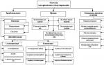
The main component of the active zone of a nuclear power reactor are fuel elements assembled into fuel assemblies (FA) and containing a certain amount of solid nuclear fuel. Now, along with the improvement of nuclear compositions, the design of fuel elements, fuel pellets is improving - through the use of manufacturing technologies, sintering, welding, chemical and mechanical processing. All this improves the operational properties of nuclear fuel, increases its reliability and safety.
A fuel element is a structural element of a nuclear reactor in which nuclear fuel is placed. Fuel rods are installed in the core of a nuclear reactor and provide the generation of the main part of thermal energy and its transfer to the coolant. More than 90% of all energy released in the reactor during nuclear fission is released inside the fuel elements and is removed by the coolant flowing around the fuel element. TVELs operate in very difficult conditions: the heat flux density from the TVEL to the coolant reaches 1-2 MW/sq.m., and the temperature fluctuates up to 3200 degrees. The most important phenomena from the point of view of analyzing the behavior of fuel rods under irradiation are swelling of the fuel and the release of gaseous fission products, changes in internal pressure, etc.
The fuel element is usually a fuel core with
sealed sheath. The cladding prevents the leakage of fission products and the interaction of the fuel with the coolant. The shell material must weakly absorb neutrons and have acceptable mechanical, hydraulic, and heat-conducting characteristics. Fuel elements are classified according to the nature of the fuel used, the shape of the fuel element, the nature of the fuel-cladding contact, and the type of nuclear reactor.
The shape and geometric dimensions of the fuel element depend on the type of reactor, as well as the manufacturing technology. The most common form of fuel rod is a long cylindrical fuel rod enclosed in a metal sheath. Some reactors use fuel elements in the form of plates (research reactors), a ball (high-temperature gas-graphite reactors), or other configurations. Some variants of fuel rod cross-sections and their mutual arrangement in the reactor core are shown in Fig.2. The arrangement of fuel rods into assemblies is carried out with the help of spacers. The fuel assembly is a structural element of the reactor core, which makes it possible to load and unload nuclear fuel.
According to the nature of the fuel and cladding, there are: fuel elements, in which the fuel and metal cladding, fuel elements consisting of ceramic fuel and a metal cladding, and all-ceramic fuel elements, covered with pyrocarbon films, included in a graphite matrix. Fuel elements are distinguished only by the nature of the fuel: metal fuel elements, in which the metallic fuel is lightly alloyed, ceramic fuel elements with ceramic fuel without diluting additives, dispersion fuel elements, in which the fuel is a highly diluted alloy or completely ceramic with a low fuel content per unit volume. According to the shape of a TVEL, lamellar ones are distinguished; solid cylindrical, wire, bar, tablet, single-ring and multi-ring, tubular; ball; lamellar; monoblock perforated. According to the method of implementing the "fuel-cladding" contact, the following are distinguished: fuel rods with mechanical contact; TVEL with metallurgical contact; Fuel rods with an intermediate layer. To increase the heat transfer surface, various types of fins can be used: longitudinal; transverse; longitudinal with straight ribs and spiral partitions; spiral; chevron.
Fuel elements are usually pellets of sintered uranium oxide in aluminum, zirconium, or stainless steel tubes; pellets of uranium alloys with zirconium, molybdenum and aluminum coated with zirconium or aluminum (in the case of an aluminum alloy); graphite tablets with dispersed uranium carbide coated with impermeable graphite.
Fig. 2. Variants of the section of fuel rods and their spacing.
For pressurized water reactors, uranium oxide pellets in stainless steel tubes are most preferred. Uranium dioxide does not react with water, has a high radiation resistance and is characterized by a high melting point. Graphite fuel cells are suitable for high-temperature gas-cooled reactors, but they have a serious drawback - gaseous fission products can penetrate through their cladding due to diffusion or defects in graphite. Organic coolants are incompatible with zirconium fuel rods and therefore require the use of aluminum alloys. The prospects for reactors with organic coolants depend on whether aluminum alloys or powder metallurgy products are created that would have the strength (at operating temperatures) and thermal conductivity necessary for the use of fins that increase heat transfer to the coolant. Since the heat transfer between the fuel and the organic coolant due to thermal conduction is small, it is desirable to use surface boiling to increase heat transfer. New problems will be associated with surface boiling, but they must be solved if the use of organic heat transfer fluids proves to be beneficial.
In addition to powders and granules, a new microspheric
granular ceramic fuel (granule diameter - a few microns), which
is used for the production of a large class of dispersed fuel elements with a cermet composition, fuel elements based on a graphite matrix, micro fuel elements with various types of coatings used in high-temperature gas-cooled nuclear reactors, as well as vibro-compacted rod fuel elements. Such fuel will apparently be used in a gas turbine modular reactor.
In a thermal reactor, fuel rods form a lattice, the free space of which
filled with retarder.
According to the nature of the fuel and cladding, fuel elements are distinguished, in which the fuel and cladding are metallic; Fuel rods consisting of ceramic fuel and metal cladding; all-ceramic fuel rods coated with pyrolytic carbon films embedded in a graphite matrix. Only by the nature of the fuel, metal fuel elements are distinguished, in which the metal fuel is lightly alloyed; ceramic fuel elements with ceramic fuel without diluting additives; dispersion fuel elements, in which the fuel is a highly dilute alloy or fully ceramic with a low fuel content per unit volume. The shape of TVELs are: lamellar; solid cylindrical (block; rod; wire, rod, tablet; single-ring and multi-ring; tubular); ball; monoblock; TVEL of other forms. According to the method of implementing the "fuel-cladding" contact, TVELs with mechanical contact are distinguished; TVEL with metallurgical contact; Fuel rods with an intermediate layer
Fuel elements of heterogeneous reactors ensure the preservation of nuclear fuel and the resulting fragments in a small enclosed space. Fuel elements are usually cast Th, U, Pu, their alloys, or a pressed mixture - ceramics or cermets - of fissile material in the form of oxide, carbide, etc. with a matrix of metals, oxides, etc. The matrix provides the necessary dilution of fissile isotopes to allowable, in terms of specific heat loads, concentrations. Heterogeneous nuclear fuel is covered on the outside with a hermetic sheath made of aluminum, zirconium or stainless steel. Sets of fuel rods in the form of plates, tubes, cylinders, rods are often combined into assemblies placed in working cells of nuclear reactors.
TVEL and TVS for VVER
In a VVER-type reactor, sintered uranium dioxide with an initial enrichment of uranium-235 in a stationary mode in the range from 2.4 to 4.4% (mass) is used as nuclear fuel. The total loading of the reactor with fuel is 75 tons.
Hexagonal fuel assemblies (FAs) contain rod-type fuel elements (TVELs) with a core of uranium dioxide in the form of pellets encased in a zirconium alloy. Inside the zirconium shell of the TVEL (inner diameter 9.1 mm, wall thickness 0.65 mm, shell material - alloy Zr + 1% Nb) there are fuel pellets with a diameter of 7.53 mm from uranium dioxide. The mass of UO2 loading in one fuel element is 1565. Guaranteed service life is 4 years. The VVER-1000 FA is a bundle of fuel rods arranged in a triangular lattice with a pitch of 12.76 mm (the bundle is enclosed in a zirconium alloy case). Some characteristics of fuel assemblies are given in Table 2. In turn, fuel assemblies are also assembled into a triangular lattice with a pitch of 147 mm (VVER-440) and 241 mm (VVER-1000).
Tab. 2. Characteristics of VVER-1000 fuel rods

The height of the fuel assembly with the bundle of control rods is 4665 mm. The fuel assembly contains 317 fuel rods, 12 guide channels for control rods, one channel for an energy release measurement sensor, and a hollow central tube. In the center of the hexagonal head of the fuel assembly there is a cylindrical bushing, in which 12 guide channels for absorbing elements and a channel for the energy release measurement sensor are mounted. The mass of fuel in the cassette is 455.5 kg. The bushing is connected to six corners of the fuel assembly head by ribs, in which spring pins are located, which serve to clamp the assembly in the reactor, compensate for thermal expansions and technological tolerances. On the faces of the head there are windows for the exit of the coolant from the FA. Unlike world analogues of FA designs based on a rectangular shape, VVER-1000 FA has a hexagonal cross section and a distribution field of fuel elements. Such a scheme of dispersion of fuel elements provides a high uniformity of the coolant flow and a more favorable
water-uranium ratio in the core. The hexagonal shape guarantees the safety of fuel assemblies during transport and technological operations in production and at nuclear power plants.
Since the commissioning of nuclear power plants with VVER, the design of fuel assemblies has undergone significant changes. At the initial stage of design and operation of fuel assemblies were with a protective sheath, i.e. hood, then assemblies with a perforated hood appeared. At present, at all NPPs with VVER-1000 type reactors being designed and under construction, preference is given to uncovered fuel assemblies. Shellless fuel assemblies improve the mixing of the coolant in the core; reduce the gap between adjacent
FA, which makes it possible to place more fuel assemblies in the same vessel volume, and thereby increase the reactor power; reduce uneven energy release due to dense packing of fuel rods; reduce the hydraulic resistance of fuel assemblies; increase the reliability of cooling in emergency modes associated with the leakage of the coolant due to the transverse flow of water from the emergency cooling system; increase the number of adjustable rods per fuel assembly in order to increase the strength properties of the load-bearing frame of the assembly and reduce the number of protection control system drives; reduce the amount of expensive material (zirconium) used in fuel assemblies.
TVEL for RBMK
Uranium dioxide 235U is used as fuel in RBMK reactors. To reduce the size of the reactor, the content of 235U in the fuel is first increased to 2.0 or 2.4% at enrichment plants. The loading of the reactor with uranium is 200 tons. The average fuel burnup is 22.3 MWt/kg.
TVEL is a zirconium tube with a height of 3.5 m and a wall thickness of 0.9 mm with 15 mm high uranium dioxide pellets enclosed in it. Two fuel assemblies connected in series, containing 18 fuel elements each, form a fuel cartridge, the length of which is 7 m. The fuel cartridge is installed in the technological channel. The number of technological channels in the reactor -1661. Water is fed into the channels from below, washes the fuel elements and heats up, and part of it turns into steam. The resulting steam-water mixture is discharged from the upper part of the channel.
The reactor is controlled by evenly distributed over the reactor
rods containing a neutron-absorbing element - boron. Rods are moving
individual servo drives in special channels, the design of which is similar to technological ones. The rods have their own cooling water circuit with a temperature of 40 - 70°C. The use of rods of various designs makes it possible to control the energy release throughout the reactor and quickly shut it down if necessary.
Fuel assemblies for fast neutron reactor, BN600
BN-600 - fast neutron reactor with sodium coolant. Electrical
power 600 MW. The design core, which consisted of fuel assemblies with
enrichment in 235U of 21% and 33%, was operated from 1980 to 1986. The maximum fuel burnup that was achieved in it was 7% of heavy atoms, i.a. Over the next two years, a transition was made to the core with three enrichment options (17%, 21% and 26% for 235U) to reduce the specific heat loads on the fuel elements. The maximum fuel burnup was increased to 8.3% t.a. The next upgrade was carried out during 1991-1993. It was based on the use of the most radiation-resistant and well-mastered by industry structural materials. After that, it was possible to achieve a fuel burnup of 10% t.a.
The core and breeding area are assembled from cassette-type hexagonal fuel assemblies with turnkey dimensions of 96 mm. The fuel assembly consists of fuel elements, a casing, a head for capturing fuel assemblies during refueling and a shank with which the fuel assemblies are installed in the socket of the pressure header and supported vertically. The fuel rods are connected to each other by fastening elements and protected by a cover that binds all parts of the fuel assembly into a single whole. The fuel elements are filled along the length of the core with bushings made of enriched uranium oxide (or a mixture of uranium oxide) and plutonium oxide, and above and below the core there are end screens made of briquettes of waste uranium oxide. The fuel rods of the breeding zone are also filled with briquettes from "waste" uranium. The gas cavities above the sodium level in the reactor are filled with argon.
Microspheres for TVELs
At present, microspherical granular materials are widely used in various industries. Of great interest is the use of microspherical ceramic materials as a fuel component of various types of fuel elements. Recently, granulated ceramic nuclear fuel has been used for the production of a large class of dispersed fuel elements with a cermet composition, fuel elements based on a graphite matrix, microfuel elements with various types of coatings used in high-temperature gas-cooled reactors, as well as vibro-compacted rod fuel elements. The main advantages of using granular microspherical fuels:
a) the possibility of creating an automated remote-controlled technological process for the preparation of recycled fuel from actinides;
b) no dust-generating operations compared to traditionally used
powder technology;
c) a more convenient form of material than powders at all stages of the technological process, which minimizes the duration of vibrocompaction;
d) microspheres can be made from a few microns to 2…3mm with careful
control them at the stage of obtaining the gel;
e) defective substandard microspherical particles can be returned to the beginning of the process;
f) microspheres of mixed oxides of actinides can be sintered to high density (more than 95% of theoretical density) at a temperature 200°C lower than the sintering temperature of pellets;
g) the possibility of obtaining and controlling microspheres with a porosity of 10 to 30% with high mechanical strength, which creates additional technological advantages.
The first technological schemes were based on powder metallurgy methods. A distinctive feature of these methods for obtaining microspherical ceramic fuel is the use of nuclear fuel powder as the starting material,
the composition of which corresponds to the final product. In the last decade intensive
methods are being developed for the production of microspherical fuels, where aqueous solutions of salts of fissile and fertile materials are used as initial products. One of the "water" methods for obtaining microspherical ceramic fuel is the sol-gel process.
The sol-gel process has several variants of gelation of actinides:
1) Gel precipitation - the process is based on the formation of an actinide gel in a working solution, in which the components that harden in an alkaline medium are evenly distributed. The method is also characterized by mass transfer.
2) External gelation - characterized by the transfer of mass through the phase boundary (sphere-forming alkaline medium - ammonia gas solution containing precipitating components). A distinction is made between direct external gelation and reverse external gelation.
3) Internal gelation - based on the fact that the working solution contains gelling additives (ammonia donors), which decompose at elevated temperatures in a sphere-forming medium. A characteristic feature of the process is the absence of mass transfer through the phase boundary.
In the process of external and internal gelation, organic liquids insoluble or slightly soluble in water are used as a dispersion medium.
Powder methods for the manufacture of fuel cores, along with the sol-gel process, have been widely developed in the technology of fuel cells for high-temperature helium reactors. The most widespread method of manufacturing products from plasticized masses. A variation of this method is the method of mechanical spheroidization of measured fuel blanks, which was chosen as the basis for developing the technology of fuel microspheres. The method consists in rolling fuel blanks from plasticized masses to perfect microspheres.