Management of the heating system. With the use of modern automation equipment
V. G. Semenov, Editor-in-Chief, Heat Supply News
The concept of a system
Everyone is used to the expressions “heat supply system”, “control system”, “ automated systems management". One of the simplest definitions of any system: a set of connected operating elements. A more complex definition is given by Academician P. K. Anokhin: “A system can only be called such a complex of selectively involved components, in which the interaction acquires the character of mutual assistance to obtain a focused useful result.” Obtaining such a result is the goal of the system, and the goal is formed on the basis of need. In a market economy, technical systems, as well as their management systems, are formed on the basis of demand, that is, a need for which someone is willing to pay.
Technical heat supply systems consist of elements (CHP, boiler houses, networks, emergency services, etc.) that have very rigid technological connections. " external environment" for technical system heat supply are consumers of different types; gas, electric, water networks; weather; new developers, etc. They exchange energy, matter and information.
Any system exists within some limits imposed, as a rule, by buyers or authorized bodies. These are the requirements for the quality of heat supply, ecology, labor safety, price restrictions.
There are active systems that can withstand negative environmental impacts (unskilled actions of administrations of different levels, competition from other projects...), and passive systems that do not have this property.
Operational systems technical management heat supply belong to typical human-machine systems, are not very complex and are quite easy to automate. In fact, they are subsystems of a higher level system - heat supply management in a limited area.
Control systems
Management is the process of purposeful influence on the system, providing an increase in its organization, the achievement of one or another useful effect. Any control system is divided into control and controlled subsystems. The connection from the control subsystem to the controlled one is called direct connection. Such a connection always exists. The opposite direction of communication is called feedback. The concept of feedback is fundamental in technology, nature and society. It is believed that control without strong feedback is not effective, because it does not have the ability to self-detect errors, formulate problems, does not allow the use of the system's self-regulation capabilities, as well as the experience and knowledge of specialists.
SA Optner even believes that control is the goal of feedback. “Feedback affects the system. Impact is a means of changing the existing state of the system by excitation of a force that allows this to be done.
In right organized system deviation of its parameters from the norm or deviation from the correct direction of development develops into feedback and initiates the control process. “The very deviation from the norm serves as an incentive to return to the norm” (P.K. Anokhin). It is also very important that one's own goal control system did not contradict the purpose of the managed system, i.e. the purpose for which it was created. It is generally accepted that the requirement of a "superior" organization is unconditional for a "lower" organization and is automatically transformed into a goal for it. This can sometimes lead to a substitution of the target.
The correct goal of the control system is the development of control actions based on the analysis of information about deviations, or, in other words, problem solving.
A problem is a situation of discrepancy between the desired and the existing. The human brain is arranged in such a way that a person begins to think in some direction only when a problem is revealed. Therefore, the correct definition of the problem predetermines the correct managerial decision. There are two categories of problems: stabilization and development.
Stabilization problems are called those, the solution of which is aimed at preventing, eliminating or compensating for disturbances that disrupt the current operation of the system. At the level of an enterprise, region or industry, the solution to these problems is referred to as production management.
The problems of development and improvement of systems are called those, the solution of which is aimed at improving the efficiency of functioning by changing the characteristics of the control object or control system.
From point of view systems approach the problem is the difference between the existing system and the desired system. The system that fills the gap between them is the object of construction and is called the solution to the problem.
Analysis of existing heat supply management systems
A systematic approach is an approach to the study of an object (problem, process) as a system in which elements, internal connections and connections with the environment are identified that affect the results of functioning, and the goals of each of the elements are determined based on the general purpose of the system.
The purpose of creating any centralized heat supply system is to provide high-quality, reliable heat supply at the lowest price. This goal suits consumers, citizens, administration and politicians. The same goal should be for the heat management system.
Today there is 2 main types of heat supply management systems:
1) administration municipality or region and the heads of state heat supply enterprises subordinate to it;
2) governing bodies of non-municipal heat supply enterprises.
Rice. 1. Generalized scheme existing system heat supply management.
A generalized diagram of the heat supply control system is shown in fig. 1. It presents only those structures ( environment), which can actually influence control systems:
Increase or decrease income;
Force to go to additional expenses;
Change the management of enterprises.
For a real analysis, we must start from the premise that only what is paid for or can be fired is performed, and not what is declared. State
There is practically no legislation regulating the activities of heat supply enterprises. Even the procedures for state regulation of local natural monopolies in heat supply are not spelled out.
Heat supply is the main problem in the reforms of housing and communal services and RAO "UES of Russia", it cannot be solved separately in either one or the other, therefore it is practically not considered, although these reforms should be interconnected precisely through heat supply. There is not even a government-approved concept for the development of the country's heat supply, let alone a real program of action.
The federal authorities do not regulate the quality of heat supply in any way, there are not even regulatory documents that define the quality criteria. Reliability of heat supply is regulated only through technical supervisory authorities. But since the interaction between them and the tariff authorities is not spelled out in any regulatory document, it is often absent. Enterprises, on the other hand, have the opportunity not to comply with any instructions, justifying this with a lack of funding.
Technical supervision according to existing regulatory documents is reduced to the control of individual technical units, and those for which there are more rules. The system in the interaction of all its elements is not considered, the measures that give the greatest system-wide effect are not identified.
The cost of heat supply is regulated only formally. Tariff legislation is so general that almost everything is left to the discretion of the federal and, to a greater extent, regional energy commissions. Heat consumption standards are regulated only for new buildings. AT government programs energy saving section on heat supply is practically absent.
As a result, the role of the state was relegated to the collection of taxes and, through supervisory authorities, information to local authorities about the shortcomings in the heat supply.
For the work of natural monopolies, for the functioning of industries that ensure the possibility of the existence of the nation, the executive branch is responsible to the parliament. The problem is not that the federal bodies are functioning unsatisfactorily, but that there is actually no structure in the structure of the federal bodies, from
The peculiarities of heat supply are the rigid mutual influence of heat supply and heat consumption modes, as well as the multiplicity of supply points for several goods (thermal energy, power, coolant, hot water). The purpose of heat supply is not to provide generation and transport, but to maintain the quality of these goods for each consumer.
This goal was achieved relatively effectively with stable coolant flow rates in all elements of the system. The “quality” regulation we use, by its very nature, implies changing only the temperature of the coolant. The emergence of demand-controlled buildings ensured the unpredictability of hydraulic regimes in networks while maintaining the constancy of costs in the buildings themselves. Complaints in the neighboring houses had to be eliminated by excessive circulation and the corresponding mass overflows.
The hydraulic calculation models used today, despite their periodic calibration, cannot provide for accounting for deviations in costs at building inputs due to changes in internal heat generation and hot water consumption, as well as the influence of sun, wind and rain. With the actual qualitative-quantitative regulation, it is necessary to “see” the system in real time and provide:
- control of the maximum number of delivery points;
- reconciliation of current balances of supply, losses and consumption;
- control action in case of unacceptable violation of modes.
Management should be as automated as possible, otherwise it is simply impossible to implement it. The challenge was to achieve this without undue expense of setting up checkpoints.
Today, when in a large number of buildings there are measuring systems with flow meters, temperature and pressure sensors, it is unreasonable to use them only for financial calculations. ACS "Teplo" is built mainly on the generalization and analysis of information "from the consumer".
When creating ACS, we overcame typical problems legacy systems:
- dependence on the correctness of calculations of metering devices and the reliability of data in unverifiable archives;
- the impossibility of bringing together operational balances due to inconsistencies in the time of measurements;
- inability to control rapidly changing processes;
- non-compliance with new requirements information security federal law "On the security of critical information infrastructure Russian Federation».
Effects from the implementation of the system:
Consumer Services:
- determination of real balances for all types of goods and commercial losses:
- determination of possible off-balance sheet income;
- control of actual power consumption and its compliance with technical specifications for connection;
- introduction of restrictions corresponding to the level of payments;
- transition to a two-part tariff;
- monitoring KPIs for all services working with consumers and assessing the quality of their work.
Exploitation:
- determination of technological losses and balances in heat networks;
- dispatching and emergency control according to actual modes;
- maintaining optimal temperature schedules;
- monitoring the state of networks;
- adjustment of heat supply modes;
- control of shutdowns and violations of modes.
Development and investment:
- reliable assessment of the results of the implementation of improvement projects;
- assessment of the effects of investment costs;
- development of heat supply schemes in real electronic models;
- optimization of diameters and network configuration;
- reduction of connection costs when taking into account real reserves bandwidth and energy saving for consumers;
- renovation planning
- organization joint work CHP and boiler houses.
Article 18. Distribution of heat load and management of heat supply systems
1. Distribution of the thermal load of consumers of thermal energy in the heat supply system between supplying thermal energy in this heat supply system, is carried out by an authority authorized in accordance with this federal law for approval of the heat supply scheme, by making annual changes to the heat supply scheme.
2. To distribute the heat load of consumers of heat energy, all heat supply organizations that own sources of heat energy in this heat supply system are required to submit to the body authorized in accordance with this Federal Law to approve the heat supply scheme, an application containing information:
1) on the amount of heat energy that the heat supply organization undertakes to supply to consumers and heat supply organizations in this heat supply system;
2) on the amount of capacity of thermal energy sources, which the heat supply organization undertakes to maintain;
3) on current tariffs in the field of heat supply and predicted specific variable costs for the production of thermal energy, heat carrier and power maintenance.
3. In the heat supply scheme, conditions must be determined under which it is possible to supply thermal energy to consumers from various sources of thermal energy while maintaining the reliability of heat supply. In the presence of such conditions, the distribution of heat load between sources of heat energy is carried out on a competitive basis in accordance with the criterion of minimum specific variable costs for the production of thermal energy by sources of thermal energy, determined in the manner established by the pricing principles in the field of heat supply, approved by the Government of the Russian Federation, on the basis of applications from organizations owning sources of thermal energy, and standards taken into account when regulating tariffs in the field of heat supply for the corresponding period of regulation.
4. If the heat supply organization does not agree with the distribution of the heat load carried out in the heat supply scheme, it has the right to appeal against the decision on such distribution, taken by the body authorized in accordance with this Federal Law to approve the heat supply scheme, to the federal executive body authorized by the Government of the Russian Federation.
5. Heat supply organizations and heat network organizations operating in the same heat supply system, annually before the start of the heating period, are required to conclude an agreement between themselves on the management of the heat supply system in accordance with the rules for organizing heat supply, approved by the Government of the Russian Federation.
6. The subject of the agreement specified in part 5 of this article is the procedure for mutual actions to ensure the functioning of the heat supply system in accordance with the requirements of this Federal Law. Mandatory conditions said agreement are:
1) determining the subordination of dispatching services of heat supply organizations and heat network organizations, the procedure for their interaction;
3) the procedure for ensuring access of the parties to the agreement or, by mutual agreement of the parties to the agreement, to another organization to heat networks for the adjustment of heat networks and regulation of the operation of the heat supply system;
4) the procedure for interaction between heat supply organizations and heat network organizations in emergency situations and emergency situations.
7. If the heat supply organizations and heat network organizations have not concluded the agreement specified in this article, the procedure for managing the heat supply system is determined by the agreement concluded for the previous heating period, and if such an agreement has not been concluded earlier, the specified procedure is established by the body authorized in accordance with this Federal law for approval of the heat supply scheme.
The article is devoted to the use of the Trace Mode SCADA system for operational remote control of district heating facilities in the city. The facility where the described project was implemented is located in the south of the Arkhangelsk region (the city of Velsk). The project provides for operational monitoring and management of the process of preparing and distributing heat for heating and supplying hot water to vital facilities of the city.
CJSC SpetsTeploStroy, Yaroslavl
Problem statement and necessary functions systems
The goal that our company faced was to build a main network for heating a large part of the city, using advanced construction methods, where pre-insulated pipes were used to build the network. For this, fifteen kilometers of main heating networks and seven central heating points (CHPs) were built. Purpose of the central heating station - using superheated water from the GT-CHP (according to the schedule 130/70 °С), it prepares the heat carrier for intra-quarter heating networks (according to the schedule 95/70 °С) and heats the water up to 60 °С for the needs of domestic hot water supply (hot water supply), The TsTP operates on an independent, closed scheme.
When setting the task, many requirements were taken into account that ensure the energy-saving principle of operation of the CHP. Here are some of the most important ones:
To carry out weather-dependent control of the heating system;
Maintain the DHW parameters at a given level (temperature t, pressure P, flow G);
Maintain at a given level the parameters of the coolant for heating (temperature t, pressure P, flow G);
Organize commercial metering of thermal energy and heat carrier in accordance with applicable normative documents(ND);
Provide ATS (automatic transfer of reserve) pumps (network and hot water supply) with motor resource equalization;
Perform correction of the main parameters according to the calendar and real time clock;
Perform periodic data transmission to the control room;
Perform diagnostics of measuring instruments and operating equipment;
Lack of staff on duty at the central heating station;
Track and report promptly service personnel about the occurrence of emergency situations.
As a result of these requirements, the functions of the operational-remote control system being created were determined. The main and aids automation and data transmission. A choice of SCADA-system was made to ensure the operability of the system as a whole.
Necessary and sufficient functions of the system:
1_Information functions:
Measurement and control of technological parameters;
Signaling and registration of parameter deviations from the established limits;
Formation and issuance of operational data to personnel;
Archiving and viewing the history of parameters.
2_Control functions:
Automatic regulation of important process parameters;
Remote control of peripheral devices (pumps);
Technological protection and blocking.
3_Service functions:
Self-diagnostics of software and hardware complex in real time;
Data transmission to the control room on schedule, upon request and in the event of an emergency;
Testing the operability and correct functioning of computing devices and input/output channels.
What influenced the choice of automation tools
and software?
The choice of basic automation tools was mainly based on three factors - this is the price, reliability and versatility of configuration and programming. So, for independent work in the central heating station and for data transmission, freely programmable controllers of the PCD2-PCD3 series from Saia-Burgess were chosen. To create a control room, the domestic SCADA system Trace Mode 6 was chosen. For data transmission, it was decided to use the usual cellular communication: use a regular voice channel for data transmission and SMS messages for prompt notification of personnel about the occurrence of emergency situations.
What is the working principle of the system
and features of the implementation of control in Trace Mode?
As in many similar systems, management functions for direct impact on regulatory mechanisms are given to the lower level, and already the management of the entire system as a whole is transferred to the upper one. I deliberately omit the description of the work of the lower level (controllers) and the process of data transfer and will go straight to the description of the upper one.
For ease of use, the control room is equipped with a personal computer (PC) with two monitors. Data from all points are collected on the dispatch controller and transmitted via the RS-232 interface to the OPC server running on a PC. The project is implemented in Trace Mode version 6 and is designed for 2048 channels. This is the first stage of the implementation of the described system.
A feature of the implementation of the task in Trace Mode is an attempt to create a multi-window interface with the ability to monitor the heat supply process in on-line mode, both on the city diagram and on the mnemonic diagrams of heat points. The use of a multi-window interface allows solving the problems of displaying a large amount of information on the dispatcher's display, which should be sufficient and at the same time non-redundant. The principle of a multi-window interface allows access to any process parameters in accordance with the hierarchical structure of windows. It also simplifies the implementation of the system at the facility, since such an interface appearance very similar to the widespread products of the Microsoft family and has similar menu equipment and toolbars familiar to any user of a personal computer.
On fig. 1 shows the main screen of the system. It schematically displays the main heating network with an indication of the heat source (CHP) and central heating points (from the first to the seventh). The screen displays information about the occurrence of emergency situations at the facilities, the current outdoor air temperature, the date and time of the last data transfer from each point. Heat supply objects are provided with pop-up hints. When an abnormal situation occurs, the object on the diagram starts to “blink”, and an event record and a red flashing indicator appear in the alarm report next to the date and time of data transmission. It is possible to view the enlarged thermal parameters for the CHP and for the entire heating network as a whole. To do this, disable the display of the list of the report of alarms and warnings (button "OTiP").

Rice. one. Main screen of the system. Scheme of the location of heat supply facilities in the city of Velsk
There are two ways to switch to the mnemonic diagram of a heat point - you need to click on the icon on the city map or on the button with the heat point inscription.
The mnemonic diagram of the substation opens on the second screen. This is done both for the convenience of monitoring a specific situation at the central heating station, and for monitoring the general state of the system. On these screens, all controlled and adjustable parameters are visualized in real time, including parameters that are read from heat meters. All technological equipment and measuring instruments are provided with pop-up hints in accordance with the technical documentation.
The image of equipment and automation means on the mnemonic diagram is as close as possible to the real view.
On the next level multi-window interface provides direct control of the heat transfer process, change settings, view the characteristics of the operating equipment, monitor the parameters in real time with a history of changes.
On fig. 2 shows a screen interface for viewing and managing the main automation tools (control controller and heat meter). On the controller management screen, it is possible to change telephone numbers for sending SMS messages, prohibit or allow the transmission of emergency and information messages, control the frequency and amount of data transmission, and set parameters for self-diagnostics of measuring instruments. On the screen of the heat meter, you can view all settings, change available settings and control the mode of data exchange with the controller.
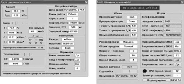
Rice. 2. Control screens for the Vzlet TSRV heat calculator and PCD253 controller
On fig. 3 shows pop-up panels for control equipment (control valve and pump groups). It displays the current status of this equipment, details of errors and some parameters necessary for self-diagnosis and verification. So, for pumps, dry-running pressure, MTBF and start-up delay are very important parameters.

Rice. 3. Control panel for pump groups and control valve
On fig. 4 shows screens for monitoring parameters and control loops in graphical form with the ability to view the history of changes. All controlled parameters of the heat substation are displayed on the parameters screen. They are grouped according to their physical meaning (temperature, pressure, flow, amount of heat, heat output, lighting). All control loops of parameters are displayed on the screen of control loops and the current value of the parameter is displayed, given the dead zone, the position of the valve and the selected control law. All this data on the screens is divided into pages, similar to the generally accepted design in Windows applications.

Rice. four. Screens for graphic display of parameters and control loops
All screens can be moved across the dual-monitor space while multi-tasking. All necessary parameters for trouble-free operation of the heat distribution system are available in real time.
How long has the system been in development?how many developers were there?
The basic part of the dispatching and control system in Trace Mode was developed within one month by the author of this article and launched in the city of Velsk. On fig. a photograph is presented from the temporary control room, where the system is installed and is undergoing trial operation. At the moment, our organization is putting into operation one more heating point and an emergency source of heat. It is at these facilities that a special control room is being designed. After its commissioning, all eight heat points will be included in the system.

Rice. 5. Temporary workplace dispatcher
During the operation of the automated process control system, various comments and wishes from the dispatching service arise. Thus, the process of updating the system is constantly underway to improve the operational properties and convenience of the dispatcher.
What is the effect of introducing such a management system?
Advantages and disadvantages
In this article, the author does not set out to evaluate economical effect from the implementation of a management system in numbers. However, the savings are obvious due to the reduction of personnel involved in the maintenance of the system, a significant reduction in the number of accidents. In addition, the environmental impact is obvious. It should also be noted that the introduction of such a system allows you to quickly respond and eliminate situations that may lead to unforeseen consequences. The payback period for the entire complex of works (construction of a heating main and heating points, installation and commissioning, automation and dispatching) for the customer will be 5-6 years.
The advantages of a working control system can be given:
Visual presentation of information on the graphic image of the object;
As for the animation elements, they were added to the project in a special way to improve the visual effect of viewing the program.
Prospects for the development of the system