Pue 7 edition pdf complete. PUE (last edition)
Chapter 1.2. POWER SUPPLY AND ELECTRIC NETWORKS
-Scope, definitions
-General requirements
- Categories of electrical receivers and ensuring the reliability of power supply
-Voltage levels and regulation, reactive power compensation
Chapter 1.7. GROUNDING AND ELECTRICAL SAFETY
-Application area.
-Terms and Definitions.
-General requirements
-Measures of protection against direct contact
-Measures of protection against direct and indirect contact
- Protective measures for indirect contact
- Grounding devices of electrical installations with voltage above 1 kV in networks with effectively grounded neutral
- Grounding devices of electrical installations with voltage above 1 kV in networks with isolated neutral
- Grounding devices of electrical installations with voltage up to 1 kV in networks with dead-earthed neutral
- Grounding devices of electrical installations with voltage up to 1 kV in networks with isolated neutral
-Grounding devices in areas with high earth resistivity
-Groundings. Ground conductors Main ground bar
- Protective conductors (P-conductors)
-Combined zero protective and zero working conductors (RELT-conductors)
- Conductors of the potential equalization system
- Connections and connections of grounding, protective conductors and conductors of the equalization and potential equalization system
- Portable electrical receivers
-Mobile electrical installations.
-Electrical installations of premises for keeping animals
Chapter 1.8. STANDARDS OF ACCEPTANCE TESTS
1.8.13. General provisions Synchronous generators and compensators DC machines
1.8.14. AC motors
1.8.15. Power transformers, autotransformers, oil reactors and grounding arc quenching reactors (arc coils)
1.8.16. Measuring current transformers
1.8.17. Instrument voltage transformers Oil circuit breakers
1.8.18. Air circuit breakers
1.8.19. SF6 circuit breakers, Vacuum circuit breakers
1.8.20. Load break switches
1.8.21. Disconnectors, separators and short circuiters
Complete switchgears for indoor and outdoor installation (KRU i-KRUN)"
1.8.26. Complete current ducts (bus ducts)
1.8.27. Busbars and connecting busbars
1.8.28. Dry current limiting reactors
1.8.29. Electrostatic precipitators
1.8.30. Capacitors
1.8.31. Valve arresters and surge arresters
1.8.32. Tubular arresters
1.8.33. Fuses, fuse-disconnectors with voltages above 1 kV
1.8.34. Bushings and bushings
1.8.35. Suspension and support insulators
1.8.36. transformer oil
1.8.37. Electrical devices, secondary circuits and electrical wiring up to 1 kV
1.8.38. Rechargeable batteries
1.8.39. Grounding devices
1.8.40. Power cable lines
Overhead power lines with voltage above 1 kV
Chapter 1.9. INSULATION OF ELECTRICAL INSTALLATIONS
-General requirements
-Insulation
External glass and porcelain insulation of electrical equipment and Qpy
Selection of insulation according to discharge characteristics
Determining the degree of pollution
Coefficients of use of the main types of insulators and insulating structures (glass and porcelain)
Section 2. POWER TRANSMISSION
Chapter 2.4. OVERHEAD POWER LINES WITH VOLTAGE UP TO 1 KB.
-Application area. Definitions
-General requirements
-Climatic conditions
-Wires. Linear reinforcement
- Arrangement of wires on supports
-Insulation
-Grounding. Surge protection
-Supports
-Dimensions, intersections and convergence.
- Intersections, convergence, joint suspension of overhead lines with communication lines of wire broadcasting and RK
- Intersections and convergence of overhead lines with engineering structures
Chapter 2.5. OVERHEAD POWER LINES
VOLTAGE ABOVE 1 KB
-Application area. Definitions
-General requirements.
- Requirements for the design of overhead lines, taking into account the peculiarities of their repair and maintenance.
-Protection of overhead lines from environmental influences
-Climatic conditions and loads
- Wires and lightning protection cables.
- The location of wires and cables and the distance between them
-Insulators and fittings
- Surge protection, grounding
- Supports and foundations
-Large transitions
- Suspension of fiber-optic communication lines on overhead lines.
- Passage of overhead lines through uninhabited and hard-to-reach areas.
- Passage of overhead lines through plantings
- Passage of overhead lines in populated areas
- Crossing and approaching overhead lines to each other
- Crossing and approaching overhead lines with communication, signaling and wire broadcasting facilities
- Crossing and approaching overhead lines with railways
- Intersection and convergence of overhead lines with highways.
- Crossing, approaching or parallel following VL with trolleybus and tram lines
-Intersection of overhead lines with bodies of water
- Passage of overhead lines on bridges
- Passage of overhead lines along dams and dams
- Approximation of overhead lines with explosive and fire hazardous installations
-Crossing and approaching overhead lines with above-ground and surface pipelines, oil and gas transport facilities and cable cars
- Intersection and approach of overhead lines with underground pipelines
- Approximation of overhead lines with airfields and heliports
-Appendix 1. Distances between wires and between wires and cables according to dance conditions
Annex 2. Reference material for chapter 2.5 PP9.
List of reference normative documents
Section 4. SWITCHGEAR AND SUBSTATIONS
Chapter 4.1. SWITCHGEAR WITH VOLTAGE UP TO 1 KB AC AND UP TO 1.5 KB DC
-Application area
-General requirements
-Installation of devices and devices
-Tires, wires, cables
-Switchgear designs
-Installation of switchgears in electrical rooms
-Installation of switchgear in industrial premises -Installation of switchgear in the open air.
Chapter 4.2. SWITCHGEAR AND SUBSTATIONS WITH VOLTAGE ABOVE 1KB
-Scope, definitions.
-General requirements. Open switchgears
-Biological protection against electric and magnetic fields
- Closed switchgears and substations
-Intrashop switchgears and transformer substations
- Complete, pole, mast transformer substations and network sectioning points
- Lightning surge protection
-Protection of rotating electrical machines against lightning surges
- Internal surge protection
-Pneumatic economy
-Oil farming
-Installation of power transformers and reactors
-Appendix. Reference material for chapter 4.2 of the PUE.
-List of reference normative documents
Section 6. ELECTRIC LIGHTING
Chapter 6.1. A COMMON PART
-Application area. Definitions
-General requirements
-Emergency lighting
-Execution and protection of lighting networks
- Protective security measures
Chapter 6.2. INTERIOR LIGHTING.
-General requirements
- Supply lighting network
- Group network
Chapter 6.3. OUTDOOR LIGHTING
-Light sources, installation of lighting fixtures and poles
- Supply of outdoor lighting installations
-Implementation and protection of outdoor lighting networks
Chapter 6.6. LIGHTING AND WIRING DEVICES
-Lighting
- Wiring devices
Section 7. ELECTRICAL EQUIPMENT FOR SPECIAL INSTALLATIONS
Chapter 7.1. ELECTRICAL INSTALLATIONS OF RESIDENTIAL, PUBLIC, ADMINISTRATIVE AND HOUSEHOLD BUILDINGS.
-Application area. Definitions. General requirements. Power supply.
- Introductory devices, switchboards, distribution points, group shields
-Wiring and cable lines
- Internal electrical equipment
-Electricity metering
- Protective security measures
Chapter 7.2. ELECTRICAL INSTALLATIONS FOR ENTERTAINMENT ENTERPRISES, CLUB ESTABLISHMENTS AND SPORTS FACILITIES
-Application area. Definitions
-General requirements. Power supply
- Electric lighting
-Power equipment,
-Laying cables and wires
- Protective security measures
Chapter 7.5. ELECTROTHERMAL INSTALLATIONS
-Application area.
-Definitions.
-General requirements
- Installations of arc furnaces of direct, indirect action and resistance arc furnaces Installations of induction and dielectric heating
- Installations of resistance furnaces of direct and indirect action
- Electron-beam installations
-Ion and laser installations.
Chapter 7.6. ELECTRIC WELDING INSTALLATIONS
-Application area
-Definitions
-General requirements
-Requirements for premises for electric welding installations and welding stations
- Installations of electric welding (cutting, surfacing) by melting
- Installations of electric welding with application of pressure
Chapter 7.10. ELECTROLYSIS AND ELECTROLYSIS PLANTS
-Application area
-Definitions. Composition of installations
-General requirements.
- Plants for electrolysis of water and aqueous solutions
- Electrolysis plants for hydrogen production (hydrogen stations)
- Electrolysis plants for chlorine production
- Magnesium electrolysis plants
- Aluminum electrolysis plants
- Installations of electrolytic refining of aluminum
- Electrolysis plants of ferroalloy production
- Electrolysis plants for nickel-cobalt production
- Copper electrolysis plants
-Electroplating installations
Chapter 1.1 General
General instructions for electrical installations
Chapter 1.2 Power supply and electrical networks
Application area. Definitions
General requirements
Categories of electrical receivers and ensuring the reliability of power supply
Voltage levels and regulation, reactive power compensation
Chapter 1.7 Grounding and Electrical Safety Measures
Application area. Terms and Definitions
General requirements
Protective measures against direct contact
Protective measures against direct and indirect contact
Protective measures for indirect contact
Grounding devices for electrical installations with voltages above 1 kV in networks with effectively grounded neutral
Grounding devices for electrical installations with voltages above 1 kV in networks with isolated neutral
Grounding devices of electrical installations with voltage up to 1 kV in networks with dead-earthed neutral
Grounding devices of electrical installations with voltage up to 1 kV in networks with isolated neutral
Grounding devices in areas with high earth resistivity
Earthing switches
Grounding conductors
Main ground bus
Protective conductors (PE conductors)
Combined zero protective and zero working conductors (PEN-conductors)
Conductors of the potential equalization system
Connections and connections of grounding, protective conductors and conductors of the potential equalization and equalization system
Portable electrical receivers
Mobile electrical installations
Electrical installations of premises for keeping animals
Chapter 1.8. Acceptance test standards
1.8.1 - 1.8.12. General provisions
1.8.13. Synchronous generators and compensators
1.8.14. DC machines
1.8.15. AC motors
1.8.16. Power transformers, autotransformers, oil reactors and grounding arc quenching reactors (arc coils)
1.8.17. Measuring current transformers
1.8.18. Measuring voltage transformers
1.8.19. Oil circuit breakers
1.8.20. Air circuit breakers
1.8.21. SF6 circuit breakers
1.8.22. Vacuum circuit breakers
1.8.23. Load break switches
1.8.24. Disconnectors, separators and short circuiters
1.8.25. Complete switchgears for indoor and outdoor installation (KRU and KRUN)
1.8.26. Complete current ducts (bus ducts)
1.8.27. Busbars and connecting busbars
1.8.28. Dry current limiting reactors
1.8.29. Electrostatic precipitators
1.8.30. Capacitors
1.8.31. Valve arresters and surge arresters
1.8.32. Tubular arresters
1.8.33. Fuses, fuse-disconnectors with voltages above 1 kV
1.8.34. Bushings and bushings
1.8.35. Suspension and support insulators
1.8.36. transformer oil
1.8.37. Electrical devices, secondary circuits and electrical wiring up to 1 kV
1.8.38. Rechargeable batteries
1.8.39. Grounding devices
1.8.40. Power cable lines
1.8.41. Overhead power lines with voltage above 1 kV
Chapter 1.9 Insulation of electrical installations
Application area. Definitions
General requirements
VL insulation
External glass and porcelain insulation of electrical equipment and outdoor switchgear
Selection of insulation according to discharge characteristics
Determining the degree of pollution
Coefficients of use of the main types of insulators and insulating structures (glass and porcelain)
Section 2. Sewerage of electricity
Chapter 2.4 Overhead power lines with voltage up to 1 kV
Application area. Definitions
General requirements
Climatic conditions
Wires. Linear reinforcement
Arrangement of wires on poles
Insulation
Grounding. Surge protection
supports
Dimensions, intersections and convergence
Intersections, convergence, joint suspension of overhead lines with communication lines, wire broadcasting and RK
Intersections and convergence of vl with engineering structures
Chapter 2.5 Overhead power lines with voltage above 1 kV
Application area. Definitions
General requirements
Requirements for the design of overhead lines, taking into account the peculiarities of their repair and maintenance
Protection of overhead lines from environmental influences
Climatic conditions and loads
Wires and lightning protection cables
The location of wires and cables and the distance between them
Insulators and fittings
Surge protection, grounding
Supports and foundations
Big transitions
Suspension of fiber-optic communication lines on overhead lines
Passage of overhead lines in uninhabited and hard-to-reach areas
Passage of overhead lines through plantings
Passage of overhead lines in populated areas
Crossing and approaching overhead lines to each other
Crossing and approaching overhead lines with communication, signaling and wire broadcasting facilities
Crossing and approaching overhead lines with railways
Crossing and approaching overhead lines with highways
Crossing, approaching or parallel following overhead lines with trolleybus and tram lines
Crossing overhead lines with water areas
Passage of overhead lines on bridges
Passage of overhead lines along dams and dikes
Rapprochement of overhead lines with explosive and fire hazardous installations
Crossing and approaching overhead lines with elevated and ground pipelines, oil and gas transport facilities and cable cars
Crossing and approaching overhead lines with underground pipelines
Rapprochement of overhead lines with airfields and heliports
Appendix. Distances between wires and between wires and cables according to dance conditions
Section 4. Switchgears and substations
Chapter 4.1 Switchgears up to 1 kV AC and up to 1.5 kV DC
Application area
General requirements
Installation of devices and devices
Tires, wires, cables
Switchgear designs
Installation of switchgears in electrical rooms
Installation of switchgears in industrial premises
Outdoor switchgear installation
Chapter 4.2 Switchgears and substations with voltages above 1 kV
Scope, definitions
General requirements
Open switchgears
Biological protection against the effects of electric and magnetic fields
Closed switchgears and substations
Intrashop switchgears and transformer substations
Complete, pole, mast transformer substations and network sectioning points
Lightning surge protection
Pneumatic economy
Oil farm
Installation of power transformers and reactors
Appendix. Reference material for chapter 4.2 of the PUE. List of reference normative documents
Section 6. Electric lighting
Chapter 6.1 General
Application area. Definitions
General requirements
Emergency lighting
Execution and protection of lighting networks
Protective security measures
Chapter 6.2 Interior lighting
General requirements
Supply lighting network
group network
Chapter 6.3 Outdoor lighting
Light sources, installation of lighting fixtures and poles
Supply of outdoor lighting installations
Execution and protection of outdoor lighting networks
Chapter 6.4 Illuminated advertising, signs and illumination
Chapter 6.5 Light Control
General requirements
Interior lighting control
Outdoor lighting control
Chapter 6.6 Lighting fixtures and wiring devices
Lighting
Wiring devices
Section 7 Electrical equipment of special installations
Chapter 7.1 Electrical installations of residential, public, administrative and domestic buildings
Application area. Definitions
Introductory devices, switchboards, distribution points, group shields
Wiring and cable lines
Internal electrical equipment
Electricity metering
Protective security measures
Chapter 7.2 Electrical installations of entertainment establishments, clubs and sports facilities
Application area. Definitions
General requirements. Power supply
electric lighting
Power equipment
Laying cables and wires
Protective security measures
Chapter 7.5 Electrothermal installations
Application area
Definitions
General requirements
Installations of arc furnaces of direct, indirect action and resistance arc furnaces
Induction and dielectric heating plants
Installations of direct and indirect resistance furnaces
Electron-beam installations
Ion and laser installations
Chapter 7.6 Electric Welding Systems
Application area
Definitions
General requirements
Requirements for premises for welding installations and welding stations
Installations of electric welding (cutting, surfacing) by melting
Electric pressure welding machines
Chapter 7.10 Electrolysis and electroplating plants
Application area
Definitions. Composition of installations
General requirements
Plants for the electrolysis of water and aqueous solutions
Electrolysis plants for hydrogen production (hydrogen stations)
Electrolysis plants for chlorine production
Magnesium electrolysis plants
Aluminum electrolysis plants
Aluminum electrolytic refining plants
Electrolysis plants of ferroalloy production
Electrolysis plants for nickel-cobalt production
Copper electrolysis plants
Electroplating plants
Application area. Terms and Definitions
1.7.1. This chapter of the Rules applies to all electrical installations of alternating and direct current with a voltage of up to 1 kV and above and contains general requirements for their grounding and protection of people and animals from electric shock both in normal operation of the electrical installation and in case of damage to the insulation.
Additional requirements are given in the relevant chapters of the EMP.
1.7.2. Electrical installations in relation to electrical safety measures are divided into:
electrical installations with voltages above 1 kV in networks with solidly grounded or effectively grounded neutral (see 1.2.16);
electrical installations with voltages above 1 kV in networks with isolated or grounded neutral through an arcing reactor or resistor;
electrical installations with voltage up to 1 kV in networks with dead-earthed neutral;
electrical installations with voltage up to 1 kV in networks with isolated neutral.
1.7.3. For electrical installations with voltage up to 1 kV, the following designations are accepted:
system TN- a system in which the neutral of the power source is solidly grounded, and the open conductive parts of the electrical installation are connected to the solidly grounded neutral of the source by means of zero protective conductors;
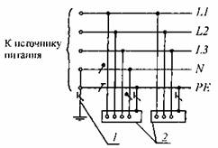
a b
Rice. 1.7.1. System TN-C variable ( a) and constant ( b) current. Zero protective and zero working conductors are combined in one conductor:
1
- grounding conductor of the neutral (middle point) of the power supply;
2
- exposed conductive parts;
3
- DC power supply
system TN-C- system TN, in which the zero protective and zero working conductors are combined in one conductor along its entire length (Fig. 1.7.1);
system TN-S- system TN, in which the zero protective and zero working conductors are separated along its entire length (Fig. 1.7.2);
system TN-C-S- system TN, in which the functions of the zero protective and zero working conductors are combined in one conductor in some part of it, starting from the power source (Fig. 1.7.3);
system IT- a system in which the neutral of the power source is isolated from the ground or grounded through devices or devices with high resistance, and the open conductive parts of the electrical installation are grounded (Fig. 1.7.4);
system TT- a system in which the neutral of the power source is solidly grounded, and the open conductive parts of the electrical installation are grounded using a grounding device that is electrically independent of the solidly grounded neutral of the source (Fig. 1.7.5).
The first letter is the state of the neutral of the power supply relative to earth:
T- grounded neutral;
I- isolated neutral.

Rice. 1.7.2. System TN-S variable ( a) and constant ( b) current. Zero protective and zero working conductors are separated:
1 1-1 1-2 2 - exposed conductive parts; 3 - source of power
The second letter is the state of open conductive parts relative to ground:
T- exposed conductive parts are earthed, regardless of the relation to earth of the neutral of the power supply or any point of the supply network;
N- exposed conductive parts are connected to a dead-earthed neutral of the power source.
Subsequent (after N) letters - combination in one conductor or separation of the functions of the zero working and zero protective conductors:
S- zero worker ( N) and zero protective ( RE) conductors are separated;


Rice. 1.7.3. System TN-C-S variable ( a) and constant ( b) current. Zero protective and zero working conductors are combined in one conductor in part of the system:
1 - grounding conductor of the neutral of the alternating current source; 1-1 - ground electrode of the output of the direct current source; 1-2 - grounding conductor of the middle point of the direct current source; 2 - exposed conductive parts, 3 - source of power
With- the functions of the zero protective and zero working conductors are combined in one conductor ( PEN-conductor);
N- - zero working (neutral) conductor;
RE- - protective conductor (grounding conductor, zero protective conductor, protective conductor of the potential equalization system);
PEN- - combined zero protective and zero working conductors.


Rice. 1.7.4. System IT variable ( a) and constant ( b) current. Exposed conductive parts of the electrical installation are earthed. The neutral of the power supply is isolated from earth or grounded through a high resistance:
1
- earthing resistance of the neutral of the power supply (if any);
2
- ground electrode;
3
- exposed conductive parts;
4
- grounding device of the electrical installation;
5
- source of power
1.7.4. An electrical network with an effectively grounded neutral is a three-phase electrical network with a voltage above 1 kV, in which the earth fault factor does not exceed 1.4.
The earth fault ratio in a three-phase electrical network is the ratio of the potential difference between an undamaged phase and earth at the earth fault point of another or two other phases to the potential difference between the phase and earth at that point before the fault.


Rice. 1.7.5. System TT variable ( a) and constant ( b) current. Exposed conductive parts of the electrical installation are grounded using grounding, electrically independent of the neutral grounding conductor:
1
- grounding conductor of the neutral of the alternating current source;
1-1
- ground electrode of the output of the direct current source;
1-2
- grounding conductor of the middle point of the direct current source;
2
- exposed conductive parts;
3
- grounding switch of open conductive parts of the electrical installation;
4
- source of power
1.7.5. Solidly grounded neutral - the neutral of a transformer or generator, connected directly to the grounding device. The output of a single-phase AC source or the pole of a DC source in two-wire networks, as well as the midpoint in three-wire DC networks, can also be dead-earthed.
1.7.6. Isolated neutral - the neutral of a transformer or generator that is not connected to a grounding device or connected to it through a high resistance of signaling, measuring, protection devices and other similar devices.
1.7.7. A conductive part is a part that can conduct an electric current.
1.7.8. Current-carrying part - the conductive part of the electrical installation, which is in the process of its operation under operating voltage, including the zero working conductor (but not PEN-conductor).
1.7.9. Open conductive part - a conductive part of an electrical installation that is accessible to the touch and is not normally energized, but which may become energized if the main insulation is damaged.
1.7.10. Third-party conductive part - a conductive part that is not part of the electrical installation.
1.7.11. Direct contact - electrical contact of people or animals with current-carrying parts that are energized.
1.7.12. Indirect touch - electrical contact of people or animals with open conductive parts that are energized when the insulation is damaged.
1.7.13. Protection against direct contact - protection to prevent contact with live parts under voltage.
1.7.14. Indirect contact protection - protection against electric shock when touching open conductive parts that are energized when the insulation is damaged.
The term insulation failure should be understood as a single insulation failure.
1.7.15. Grounding conductor - a conductive part or a set of interconnected conductive parts that are in electrical contact with the ground directly or through an intermediate conductive medium.
1.7.16. Artificial ground electrode - a ground conductor specially made for grounding purposes.
1.7.17. Natural ground conductor - a third-party conductive part that is in electrical contact with the ground directly or through an intermediate conductive medium used for grounding purposes.
1.7.18. Grounding conductor - a conductor connecting the grounded part (point) with the ground electrode.
1.7.19. Grounding device - a combination of grounding and grounding conductors.
1.7.20. Zero potential zone (relative earth) - a part of the earth that is outside the zone of influence of any grounding conductor, the electric potential of which is assumed to be zero.
1.7.21. Spreading zone (local earth) - the earth zone between the ground electrode and the zone of zero potential.
The term earth used in the chapter should be understood as earth in the spreading zone.
1.7.22. An earth fault is an accidental electrical contact between energized live parts and earth.
1.7.23. The voltage on the grounding device is the voltage that occurs when current drains from the ground electrode into the ground between the point of current input into the ground electrode and the zone of zero potential.
1.7.24. Touch voltage - the voltage between two conductive parts or between a conductive part and the ground when a person or animal touches them at the same time.
Expected touch voltage - the voltage between conductive parts that are simultaneously accessible to touch when a person or animal does not touch them.
1.7.25. Step voltage - the voltage between two points on the surface of the earth, at a distance of 1 m from one another, which is taken equal to the length of a person's step.
1.7.26. The resistance of the grounding device is the ratio of the voltage on the grounding device to the current flowing from the grounding conductor into the ground.
1.7.27. Equivalent resistivity of the earth with a heterogeneous structure - the electrical resistivity of the earth with a homogeneous structure, in which the resistance of the grounding device has the same value as in the earth with a heterogeneous structure.
The term resistivity used in the chapter for non-homogeneous earth should be understood as equivalent resistivity.
1.7.28. Grounding - the intentional electrical connection of any point in the network, electrical installation or equipment with a grounding device.
1.7.29. Protective grounding - grounding performed for electrical safety purposes.
1.7.30. Working (functional) grounding - grounding of a point or points of current-carrying parts of an electrical installation, performed to ensure the operation of an electrical installation (not for electrical safety purposes).
1.7.31. Protective grounding in electrical installations with voltage up to 1 kV - a deliberate connection of open conductive parts with a dead-earthed neutral of a generator or transformer in three-phase current networks, with a dead-earthed output of a single-phase current source, with a grounded source point in DC networks, performed for electrical safety purposes.
1.7.32. Potential equalization - electrical connection of conductive parts to achieve equality of their potentials.
Protective equalization of potentials - equalization of potentials, performed for the purpose of electrical safety.
The term potential equalization used in the chapter should be understood as protective potential equalization.
1.7.33. Potential equalization - reducing the potential difference (step voltage) on the surface of the earth or floor with the help of protective conductors laid in the ground, in the floor or on their surface and connected to a grounding device, or by using special earth coatings.
1.7.34. Protective ( RE) conductor - a conductor intended for electrical safety purposes.
Protective earth conductor - a protective conductor intended for protective earthing.
Potential equalization protective conductor - a protective conductor designed for protective potential equalization.
Zero protective conductor - a protective conductor in electrical installations up to 1 kV, designed to connect open conductive parts to a solidly grounded neutral of a power source.
1.7.35. Zero working (neutral) conductor ( N) - a conductor in electrical installations up to 1 kV, designed to power electrical receivers and connected to a solidly grounded neutral of a generator or transformer in three-phase current networks, with a solidly grounded output of a single-phase current source, with a solidly grounded source point in DC networks.
1.7.36. Combined zero protective and zero working ( PEN) conductors - conductors in electrical installations with voltage up to 1 kV, combining the functions of zero protective and zero working conductors.
1.7.37. The main grounding bus is a bus that is part of the grounding device of an electrical installation up to 1 kV and is designed to connect several conductors for the purpose of grounding and potential equalization.
1.7.38. Protective automatic power off - automatic opening of the circuit of one or more phase conductors (and, if required, the zero working conductor), performed for electrical safety purposes.
The term auto power off as used in the chapter should be understood as protective auto power off.
1.7.39. Basic insulation - insulation of current-carrying parts, providing, among other things, protection against direct contact.
1.7.40. Additional insulation - independent insulation in electrical installations with voltage up to 1 kV, performed in addition to the main insulation for protection against indirect contact.
1.7.41. Double insulation - insulation in electrical installations with voltage up to 1 kV, consisting of basic and additional insulation.
1.7.42. Reinforced insulation - insulation in electrical installations with voltage up to 1 kV, providing a degree of protection against electric shock equivalent to double insulation.
1.7.43. Extra low (low) voltage (SLV) - voltage not exceeding 50 V AC and 120 V DC.
1.7.44. Isolating transformer - a transformer, the primary winding of which is separated from the secondary windings by means of protective electrical separation of circuits.
1.7.45. Safety isolating transformer is an isolating transformer designed to supply extra-low voltage circuits.
1.7.46. Protective screen - a conductive screen designed to separate an electrical circuit and / or conductors from the current-carrying parts of other circuits.
1.7.47. Protective electrical separation of circuits - separation of one electrical circuit from other circuits in electrical installations with voltage up to 1 kV using:
- double insulation;
- basic insulation and protective screen;
- reinforced insulation.
1.7.48. Non-conductive (insulating) premises, zones, sites - premises, zones, sites in which (on which) protection in case of indirect contact is provided by high resistance of the floor and walls and in which there are no grounded conductive parts.
General requirements
1.7.49. The current-carrying parts of the electrical installation should not be accessible for accidental contact, and the open and third-party conductive parts accessible to touch should not be energized, which poses a risk of electric shock both in the normal operation of the electrical installation and in case of damage to the insulation.
1.7.50. To protect against electric shock in normal operation, the following protective measures against direct contact must be applied individually or in combination:
- basic insulation of current-carrying parts;
- enclosures and shells;
- setting up barriers;
- placement out of reach;
- the use of ultra-low (small) voltage.
For additional protection against direct contact in electrical installations with voltages up to 1 kV, if there are requirements of other chapters of the PUE, residual current devices (RCDs) with a rated differential breaking current of not more than 30 mA should be used.
1.7.51. In order to protect against electric shock in the event of insulation failure, the following protective measures against indirect contact must be applied individually or in combination:
- protective grounding;
- automatic power off;
- equalization of potentials;
- potential equalization;
- double or reinforced insulation;
- ultra-low (small) voltage;
- protective electrical separation of circuits;
- insulating (non-conductive) rooms, zones, sites.
1.7.52. Measures of protection against electric shock must be provided in the electrical installation or part of it, or applied to individual electrical receivers and can be implemented in the manufacture of electrical equipment, or during installation of the electrical installation, or in both cases.
The use of two or more protective measures in an electrical installation should not have a mutual influence that reduces the effectiveness of each of them.
1.7.53. Protection against indirect contact must be carried out in all cases if the voltage in the electrical installation exceeds 50 V AC and 120 V DC.
In rooms with increased danger, especially dangerous and in outdoor installations, protection against indirect contact may be required at lower voltages, for example, 25 V AC and 60 V DC or 12 V AC and 30 V DC, subject to the requirements of the relevant chapters of the PUE.
Protection against direct contact is not required if the electrical equipment is located in the area of the potential equalization system, and the highest operating voltage does not exceed 25 V AC or 60 V DC in rooms without increased danger and 6 V AC or 15 V DC - in all cases.
Note. Here and throughout the chapter, AC voltage refers to the rms value of AC voltage; DC voltage - DC or rectified current voltage with a ripple content of not more than 10% of the rms value.
1.7.54. For grounding electrical installations, artificial and natural grounding conductors can be used. If, when using natural grounding conductors, the resistance of the grounding devices or the contact voltage has an acceptable value, and the normalized values of the voltage on the grounding device and the permissible current densities in natural grounding conductors are provided, the implementation of artificial grounding conductors in electrical installations up to 1 kV is not necessary. The use of natural grounding conductors as elements of grounding devices should not lead to their damage when short-circuit currents flow through them or to disruption of the operation of the devices with which they are connected.
1.7.55. For grounding in electrical installations of different purposes and voltages, geographically close, as a rule, one common grounding device should be used.
A grounding device used for grounding electrical installations of the same or different purposes and voltages must meet all the requirements for grounding these electrical installations: protecting people from electric shock if the insulation is damaged, operating conditions of networks, protecting electrical equipment from overvoltage, etc. in throughout the entire period of operation.
First of all, the requirements for protective earthing must be observed.
Grounding devices for protective grounding of electrical installations of buildings and structures and lightning protection of the 2nd and 3rd categories of these buildings and structures, as a rule, should be common.
When making a separate (independent) earthing switch for working grounding, under the conditions of operation of information or other equipment sensitive to interference, special measures must be taken to protect against electric shock, excluding simultaneous contact with parts that may be under a dangerous potential difference if the insulation is damaged.
To combine grounding devices of different electrical installations into one common grounding device, natural and artificial grounding conductors can be used. Their number must be at least two.
1.7.56. The required values of contact voltage and resistance of grounding devices when ground fault currents and leakage currents flow from them must be provided under the most unfavorable conditions at any time of the year.
When determining the resistance of grounding devices, artificial and natural grounding conductors should be taken into account.
When determining the resistivity of the earth, its seasonal value corresponding to the most unfavorable conditions should be taken as the calculated one.
Grounding devices must be mechanically strong, thermally and dynamically resistant to earth fault currents.
1.7.57. Electrical installations up to 1 kV in residential, public and industrial buildings and outdoor installations should, as a rule, be powered from a source with a solidly grounded neutral using a system TN.
To protect against electric shock in case of indirect contact in such electrical installations, automatic power off must be performed in accordance with 1.7.78-1.7.79.
System selection requirements TN-C, TN-S, TN-C-S for specific electrical installations are given in the relevant chapters of the Rules.
1.7.58. Power supply of electrical installations with voltage up to 1 kV AC from a source with isolated neutral using the system IT should be carried out, as a rule, if a power interruption is unacceptable at the first short circuit to the ground or to open conductive parts connected to the potential equalization system. In such electrical installations, for protection against indirect contact during the first earth fault, protective grounding must be performed in combination with network insulation monitoring or RCDs with a rated differential breaking current of not more than 30 mA should be used. In the event of a double earth fault, automatic power off shall be performed in accordance with 1.7.81.
1.7.59. Power supply of electrical installations with voltage up to 1 kV from a source with a dead-earthed neutral and with grounding of open conductive parts using a ground electrode not connected to the neutral (system TT), is allowed only in cases where the electrical safety conditions in the system TN cannot be provided. For protection against indirect contact in such electrical installations, automatic power off must be performed with the mandatory use of RCDs. In this case, the following condition must be met:
R a I a £ 50 V,
where I a - tripping current of the protective device;
R a - the total resistance of the grounding conductor and the grounding conductor, when using RCD to protect several electrical receivers - the grounding conductor of the most distant electrical receiver.
1.7.60. When using a protective automatic power off, the main potential equalization system must be made in accordance with 1.7.82, and, if necessary, an additional potential equalization system in accordance with 1.7.83.
1.7.61. When using the system TN re-grounding is recommended RE- and РEN- conductors at the input to the electrical installations of buildings, as well as in other accessible places. For re-grounding, natural grounding should be used first. The resistance of the re-grounding earth electrode is not standardized.
Inside large and multi-storey buildings, a similar function is performed by potential equalization by connecting a zero protective conductor to the main ground bus.
Re-grounding of electrical installations with voltage up to 1 kV, powered by overhead lines, must be carried out in accordance with 1.7.102-1.7.103.
1.7.62. If the automatic power off time does not meet the conditions 1.7.78-1.7.79 for the system TN and 1.7.81 for the system IT, then indirect contact protection for individual parts of the electrical installation or individual electrical receivers can be performed using double or reinforced insulation (class II electrical equipment), extra-low voltage (class III electrical equipment), electrical separation of circuits of insulating (non-conductive) rooms, zones, sites.
1.7.63. System IT voltage up to 1 kV, connected through a transformer to a network with a voltage above 1 kV, must be protected by a breakdown fuse from the danger arising from damage to the insulation between the windings of the higher and lower voltages of the transformer. A blowout fuse must be installed in the neutral or phase on the low voltage side of each transformer.
1.7.64. In electrical installations with a voltage above 1 kV with an isolated neutral, to protect against electric shock, protective grounding of exposed conductive parts must be made.
In such electrical installations, it should be possible to quickly detect ground faults. Ground fault protection should be installed with a tripping action throughout the entire electrically connected network in cases where this is necessary for safety reasons (for lines supplying mobile substations and mechanisms, peat mines, etc.).
1.7.65. In electrical installations with voltages above 1 kV with an effectively grounded neutral, protective grounding of exposed conductive parts must be made to protect against electric shock.
1.7.66. Protective zeroing in the system TN and protective earth in the system IT electrical equipment installed on overhead line supports (power and instrument transformers, disconnectors, fuses, capacitors and other devices) must be performed in compliance with the requirements given in the relevant chapters of the PUE, as well as in this chapter.
The resistance of the grounding device of the overhead line support on which the electrical equipment is installed must comply with the requirements of Ch. 2.4 and 2.5.
Protective measures against direct contact
1.7.67. The basic insulation of live parts must cover the live parts and withstand all possible influences to which it may be subjected during its operation. Removal of the insulation should only be possible by destroying it. Paint coatings are not insulation against electric shock, except as specifically stated in the specifications for specific products. When performing insulation during installation, it must be tested in accordance with the requirements of Ch. 1.8.
In cases where the main insulation is provided by an air gap, protection against direct contact with current-carrying parts or approaching them at a dangerous distance, including in electrical installations with voltages above 1 kV, must be carried out by means of shells, fences, barriers or placement out of reach.
1.7.68. Fencing and enclosures in electrical installations with voltage up to 1 kV must have a degree of protection of at least IP 2X, except in cases where large gaps are necessary for the normal operation of electrical equipment.
Enclosures and enclosures must be securely fastened and have sufficient mechanical strength.
Entry beyond the fence or opening the shell should be possible only with the help of a special key or tool, or after removing the voltage from the current-carrying parts. If these conditions cannot be met, intermediate guards with a degree of protection of at least IP 2X should be installed, the removal of which should also be possible only with the help of a special key or tool.
1.7.69. Barriers are designed to protect against accidental contact with live parts in electrical installations with voltage up to 1 kV or approaching them at a dangerous distance in electrical installations with voltage above 1 kV, but do not exclude deliberate contact and approach to live parts when bypassing the barrier. Barriers do not require a wrench or tool to be removed, but they must be secured so that they cannot be removed unintentionally. Barriers must be of insulating material.
1.7.70. Placement out of reach to protect against direct contact with live parts in electrical installations with voltage up to 1 kV or approaching them at a dangerous distance in electrical installations with voltage above 1 kV can be applied if it is impossible to fulfill the measures specified in 1.7.68-1.7.69, or their insufficiency. In this case, the distance between conductive parts accessible to simultaneous contact in electrical installations with voltage up to 1 kV must be at least 2.5 m. There should not be parts within the reach area that have different potentials and are accessible to simultaneous contact.
In the vertical direction, the reach zone in electrical installations with voltage up to 1 kV should be 2.5 m from the surface on which people are located (Fig. 1.7.6).
The indicated dimensions do not include the use of aids (eg tools, ladders, long objects).
1.7.71. Installation of barriers and placement out of reach is allowed only in areas accessible to qualified personnel.
1.7.72. In electrical rooms of electrical installations with voltages up to 1 kV, protection against direct contact is not required if the following conditions are simultaneously met:
these rooms are clearly marked and can only be accessed with a key;
the possibility of free exit from the premises without a key is provided, even if it is locked from the outside;
the minimum dimensions of service passages correspond to Ch. 4.1.

Rice. 1.7.6. Reach zone in electrical installations up to 1 kV:
S- the surface on which a person can be;
AT- base surface S;
The boundary of the reach zone of current-carrying parts by the hand of a person located on the surface S;
0.75; 1.25; 2.50 m - distance from the edge of the surface S to the edge of reach
Protective measures against direct and indirect contact
1.7.73. Extra low (low) voltage (SLV) in electrical installations with voltage up to 1 kV can be used to protect against electric shock during direct and / or indirect contact in combination with protective electrical circuit separation or in combination with automatic power off.
In both cases, a safety isolating transformer in accordance with GOST 30030 “Isolating transformers and safety isolating transformers” or another source of SLV that provides an equivalent degree of safety should be used as a power source for the SLV circuits in both cases.
The live parts of the ELV circuits must be electrically separated from other circuits so that an electrical separation equivalent to that between the primary and secondary windings of an isolating transformer is ensured.
The conductors of the SLV circuits, as a rule, must be laid separately from conductors of higher voltages and protective conductors, either separated from them by a grounded metal screen (sheath), or enclosed in a non-metallic sheath in addition to the main insulation.
Plugs and sockets of plug connectors in ELV circuits must not allow connection to sockets and plugs of other voltages.
Plug sockets must be without protective contact.
For VLV values above 25 V a.c. or 60 V d.c., protection against direct contact shall also be provided by means of guards or enclosures or insulation suitable for a test voltage of 500 V a.c. for 1 min.
1.7.74. When using SLV in combination with electrical separation of circuits, exposed conductive parts must not be intentionally connected to the earth electrode, protective conductors or exposed conductive parts of other circuits and to third-party conductive parts, unless the connection of third-party conductive parts to electrical equipment is necessary, and the voltage on these parts cannot exceed the CNN value.
SLV in combination with electrical separation of circuits should be used when using SLV it is necessary to provide protection against electric shock if the insulation is damaged not only in the SLV circuit, but also if the insulation is damaged in other circuits, for example, in the circuit supplying the source.
When using SLV in combination with automatic power off, one of the outputs of the SLV source and its case must be connected to the protective conductor of the circuit supplying the source.
1.7.75. In cases where the electrical installation uses electrical equipment with the highest operating (functional) voltage not exceeding 50 V AC or 120 V DC, such voltage can be used as a measure of protection against direct and indirect contact, if the requirements of 1.7.73 are met. -1.7.74.
Protective measures for indirect contact
1.7.76. Protection requirements for indirect contact apply to:
1) cases of electrical machines, transformers, devices, lamps, etc.;
2) drives of electrical apparatus;
3) frames of switchboards, control panels, shields and cabinets, as well as removable or opening parts, if the latter are equipped with electrical equipment with a voltage above 50 V AC or 120 V DC (in cases provided for by the relevant chapters of the PUE - above 25 V AC or 60 V DC);
4) metal structures of switchgears, cable structures, cable boxes, sheaths and armor of control and power cables, sheaths of wires, sleeves and pipes of electrical wiring, sheaths and supporting structures of bus ducts (bus ducts), trays, boxes, strings, cables and strips on which reinforced cables and wires (except for strings, cables and strips along which cables with grounded or grounded metal sheath or armor are laid), as well as other metal structures on which electrical equipment is installed;
5) metal sheaths and armor of control and power cables and wires for voltages not exceeding those specified in 1.7.53, laid on common metal structures, including common pipes, boxes, trays, etc., with cables and wires on higher voltages;
6) metal cases of mobile and portable power receivers;
7) electrical equipment installed on moving parts of machine tools, machines and mechanisms.
When used as a protective measure for automatic power off, these exposed conductive parts must be connected to a solidly earthed neutral of the power supply in the system. TN and grounded in systems IT and TT.
1.7.77. No need to intentionally connect to source neutral in the system TN and ground in systems IT and TT:
1) enclosures of electrical equipment and apparatus installed on metal bases: structures, switchgear, switchboards, cabinets, machine beds, machines and mechanisms connected to the neutral of the power source or grounded, while ensuring reliable electrical contact of these enclosures with the bases;
2) the structures listed in 1.7.76, while ensuring reliable electrical contact between these structures and the electrical equipment installed on them, connected to the protective conductor;
3) removable or opening parts of the metal frames of switchgear chambers, cabinets, fences, etc., if no electrical equipment is installed on the removable (opening) parts or if the voltage of the installed electrical equipment does not exceed the values specified in 1.7.53;
4) fittings of insulators of overhead power lines and fasteners attached to it;
5) open conductive parts of electrical equipment with double insulation;
6) metal brackets, fasteners, pipe sections of mechanical protection of cables in places where they pass through walls and ceilings and other similar parts of electrical wiring with an area of up to 100 cm 2, including pull-through and branch boxes of hidden electrical wiring.
1.7.78. When performing automatic power off in electrical installations with voltage up to 1 kV, all exposed conductive parts must be connected to a solidly grounded neutral of the power source, if the system is used TN, and grounded if systems are applied IT or TT. At the same time, the characteristics of protective devices and the parameters of protective conductors must be coordinated in order to ensure a normalized time for disconnecting a damaged circuit by a protective switching device in accordance with the rated phase voltage of the supply network.
In electrical installations in which automatic power off is applied as a protective measure, potential equalization must be carried out.
For automatic power off, protective switching devices that respond to overcurrents or differential currents can be used.
1.7.79. In system TN the time of automatic power off should not exceed the values specified in Table. 1.7.1.
Table 1.7.1
TN
The given disconnection times are considered sufficient to ensure electrical safety, including in group circuits supplying mobile and portable electrical receivers and handheld power tools of class 1.
In circuits supplying distribution, group, floor and other boards and boards, the shutdown time should not exceed 5 s.
Off-time values are allowed more than those indicated in Table. 1.7.1, but not more than 5 s in circuits supplying only stationary electrical receivers from switchboards or shields when one of the following conditions is met:
1) the total resistance of the protective conductor between the main ground bus and the switchboard or shield does not exceed the value, Ohm:
50× Z c / U 0 ,
where Z c - total resistance of the "phase-zero" circuit, Ohm;
U 0 - nominal phase voltage of the circuit, V;
50 - voltage drop in the section of the protective conductor between the main ground bus and the switchboard or shield, V;
2) to the bus RE switchboard or shield, an additional potential equalization system is connected, covering the same third-party conductive parts as the main potential equalization system.
It is allowed to use RCDs that respond to differential current.
1.7.80. It is not allowed to use RCDs that respond to differential current in four-wire three-phase circuits (system TN-C). If it is necessary to use RCDs to protect individual electrical receivers powered by the system TN-C, protective RE- the conductor of the electrical receiver must be connected to PEN- the conductor of the circuit supplying the electrical receiver to the protective switching device.
1.7.81. In system IT the time of automatic power off in case of a double circuit to open conductive parts must comply with Table. 1.7.2.
Table 1.7.2
The longest allowable protective shutdown time for the system IT
1.7.82. The main potential equalization system in electrical installations up to 1 kV must interconnect the following conductive parts (Fig. 1.7.7):
1) zero protective RE- or REN- the conductor of the supply line in the system TN;
2) a ground conductor connected to the grounding device of the electrical installation, in systems IT and TT;
3) a grounding conductor connected to the re-grounding conductor at the entrance to the building (if there is a grounding conductor);
4) metal pipes of communications included in the building: hot and cold water supply, sewerage, heating, gas supply, etc.
If the gas supply pipeline has an insulating insert at the entrance to the building, only that part of the pipeline that is relative to the insulating insert from the side of the building is connected to the main potential equalization system;
5) metal parts of the building frame;
6) metal parts of centralized ventilation and air conditioning systems. In the presence of decentralized ventilation and air conditioning systems, metal air ducts should be connected to the bus RE power supply panels for fans and air conditioners;

Rice. 1.7.7. Potential equalization system in the building:
M- open conductive part; C1- metal water pipes entering the building; C2- metal sewer pipes entering the building; C3- metal gas supply pipes with an insulating insert at the inlet, entering the building; C4- ventilation and air conditioning ducts; C5- heating system; C6- metal water pipes in the bathroom; C7- metal bath; C8- third-party conductive part within reach of exposed conductive parts; C9- reinforcement of reinforced concrete structures; GZSH - main ground bus; T1- natural grounding; T2- lightning protection ground electrode (if any); 1 - zero protective conductor; 2 - conductor of the main potential equalization system; 3 - conductor of an additional potential equalization system; 4 - down conductor of the lightning protection system; 5 - contour (main) of working grounding in the room of information computing equipment; 6 - conductor of working (functional) grounding; 7 - potential equalization conductor in the working (functional) grounding system; 8 - ground conductor
7) grounding device of the lightning protection system of the 2nd and 3rd categories;
8) a grounding conductor of functional (working) grounding, if there is one and there are no restrictions on connecting the working grounding network to a protective grounding grounding device;
9) metal sheaths of telecommunication cables.
Conductive parts entering the building from the outside should be connected as close as possible to their point of entry into the building.
To connect to the main potential equalization system, all of these parts must be connected to the main ground bus (1.7.119-1.7.120) using the conductors of the potential equalization system.
1.7.83. The system of additional potential equalization must interconnect all open conductive parts of stationary electrical equipment that are simultaneously accessible to the touch and third-party conductive parts, including metal parts of the building structures accessible to touch, as well as zero protective conductors in the system TN and protective earth conductors in systems IT and TT, including protective conductors of socket outlets.
For potential equalization, specially provided conductors or open and third-party conductive parts can be used if they meet the requirements of 1.7.122 for protective conductors with respect to conductivity and continuity of the electrical circuit.
1.7.84. Protection by means of double or reinforced insulation may be ensured by the use of class II electrical equipment or by enclosing electrical equipment having only basic insulation of live parts in an insulating sheath.
Conductive parts of equipment with double insulation must not be connected to the protective conductor and to the potential equalization system.
1.7.85. Protective electrical separation of circuits should be used, as a rule, for one circuit.
The highest operating voltage of the separated circuit must not exceed 500 V.
The circuit to be separated must be powered from an isolating transformer complying with GOST 30030 "Isolating transformers and safety isolating transformers", or from another source that provides an equivalent degree of safety.
Current-carrying parts of a circuit powered by an isolating transformer must not be connected to grounded parts and protective conductors of other circuits.
Conductors of circuits powered by an isolating transformer are recommended to be laid separately from other circuits. If this is not possible, then for such circuits it is necessary to use cables without a metal sheath, armor, screen or insulated wires laid in insulating pipes, boxes and channels, provided that the rated voltage of these cables and wires corresponds to the highest voltage of the jointly laid circuits, and each circuit protected from overcurrents.
If only one electrical receiver is supplied from an isolating transformer, then its exposed conductive parts must not be connected either to the protective conductor or to the open conductive parts of other circuits.
It is allowed to supply several electrical receivers from one isolation transformer, provided that the following conditions are met simultaneously:
1) exposed conductive parts of the circuit to be separated must not have electrical connection with the metal case of the power source;
2) the open conductive parts of the circuit to be separated must be interconnected by insulated ungrounded conductors of the local potential equalization system that does not have connections with protective conductors and open conductive parts of other circuits;
3) all socket outlets must have a protective contact connected to a local ungrounded potential equalization system;
4) all flexible cables, with the exception of those supplying class II equipment, must have a protective conductor used as a potential equalization conductor;
5) the shutdown time of the protective device in case of a two-phase short circuit to open conductive parts should not exceed the time specified in Table. 1.7.2.
1.7.86. Insulating (non-conductive) rooms, zones and sites can be used in electrical installations with voltage up to 1 kV, when the requirements for automatic power off cannot be met, and the use of other protective measures is impossible or impractical.
The resistance relative to the local ground of the insulating floor and walls of such premises, zones and sites at any point must be at least:
50 kOhm at a rated voltage of the electrical installation up to 500 V inclusive, measured with a megohmmeter for a voltage of 500 V;
100 kOhm at a rated voltage of the electrical installation of more than 500 V, measured with a megaohmmeter for a voltage of 1000 V.
If the resistance at any point is less than specified, such rooms, areas, areas should not be considered as a measure of protection against electric shock.
For insulating (non-conductive) rooms, zones, sites, it is allowed to use electrical equipment of class 0, subject to at least one of the following three conditions:
1) open conductive parts are removed from one another and from third-party conductive parts by at least 2 m. It is allowed to reduce this distance out of reach to 1.25 m;
2) exposed conductive parts are separated from external conductive parts by barriers of insulating material. At the same time, distances not less than those specified in paragraphs. 1, must be secured on one side of the barrier;
3) third-party conductive parts are covered with insulation that can withstand a test voltage of at least 2 kV for 1 min.
No protective conductor shall be provided in insulating rooms (zones).
Measures must be taken to prevent potential drift to third-party conductive parts of the room from the outside.
The floor and walls of such rooms should not be exposed to moisture.
1.7.87. When performing protection measures in electrical installations with voltage up to 1 kV, the classes of electrical equipment used according to the method of protecting a person from electric shock according to GOST 12.2.007.0 “SSBT. Electrical products. General safety requirements" should be taken in accordance with Table. 1.7.3.
Table 1.7.3
The use of electrical equipment in electrical installations with voltage up to 1 kV
Class according to GOST 12.2.007.0 R IEC536 |
Marking |
Purpose of protection |
Conditions for the use of electrical equipment in an electrical installation |
On indirect contact |
1. Application in non-conductive rooms. |
||
Safety clip - sign or letters RE, or yellow-green stripes |
On indirect contact |
Connecting the grounding clamp of electrical equipment to the protective conductor of the electrical installation |
|
On indirect contact |
Regardless of the protective measures taken in the electrical installation |
||
From direct and indirect contact |
Powered by a safety isolating transformer |
Grounding devices for electrical installations with voltages above 1 kV in networks with effectively grounded neutral
1.7.88. Grounding devices of electrical installations with voltages above 1 kV in networks with an effectively grounded neutral should be made in compliance with the requirements either for their resistance (1.7.90) or for touch voltage (1.7.91), as well as in compliance with the requirements for design (1.7.92 -1.7.93) and to limit the voltage on the grounding device (1.7.89). Requirements 1.7.89-1.7.93 do not apply to grounding devices of overhead lines.
1.7.89. The voltage on the grounding device when the earth fault current drains from it should, as a rule, not exceed 10 kV. Voltage above 10 kV is allowed on grounding devices, from which the removal of potentials outside buildings and external fences of electrical installations is excluded. When the voltage on the grounding device is more than 5 kV, measures must be taken to protect the insulation of the outgoing communication and telemechanics cables and to prevent the removal of dangerous potentials outside the electrical installation.
1.7.90. The grounding device, which is carried out in compliance with the requirements for its resistance, must have a resistance of no more than 0.5 Ohm at any time of the year, taking into account the resistance of natural and artificial grounding conductors.
In order to equalize the electrical potential and ensure the connection of electrical equipment to the ground electrode in the territory occupied by the equipment, longitudinal and transverse horizontal ground electrodes should be laid and combined into a ground grid.
Longitudinal grounding conductors should be laid along the axes of electrical equipment from the service side at a depth of 0.5-0.7 m from the ground surface and at a distance of 0.8-1.0 m from foundations or equipment foundations. It is allowed to increase the distances from the foundations or bases of the equipment up to 1.5 m with the laying of one ground electrode for two rows of equipment, if the service sides face each other, and the distance between the bases or foundations of the two rows does not exceed 3.0 m.
Transverse ground electrodes should be laid in convenient places between equipment at a depth of 0.5-0.7 m from the ground. The distance between them is recommended to be taken as increasing from the periphery to the center of the grounding grid. In this case, the first and subsequent distances, starting from the periphery, should not exceed 4.0, respectively; 5.0; 6.0; 7.5; 9.0; 11.0; 13.5; 16.0; 20 m.
Horizontal grounding conductors should be laid along the edge of the territory occupied by the grounding device so that they together form a closed loop.
If the circuit of the grounding device is located within the external fence of the electrical installation, then at the entrances and entrances to its territory, the potential should be equalized by installing two vertical ground electrodes connected to an external horizontal ground electrode opposite the entrances and entrances. Vertical earthing should be 3-5 m long, and the distance between them should be equal to the width of the entrance or entrance.
1.7.91. The grounding device, which is carried out in compliance with the requirements for the contact voltage, must provide at any time of the year when the ground fault current drains from it, the contact voltage values \u200b\u200bthat do not exceed the rated ones (see GOST 12.1.038). In this case, the resistance of the grounding device is determined by the allowable voltage on the grounding device and the ground fault current.
When determining the value of the allowable contact voltage, the sum of the protection action time and the total switch off time should be taken as the estimated exposure time. When determining the permissible values of contact voltage at workplaces where, during the production of operational switching, short circuits may occur on structures that are accessible to touch by the personnel performing the switching, the duration of the backup protection should be taken, and for the rest of the territory - the main protection.
Note. The workplace should be understood as a place for the operational maintenance of electrical devices.
The placement of longitudinal and transverse horizontal grounding conductors should be determined by the requirements for limiting contact voltages to normalized values and the convenience of connecting grounded equipment. The distance between longitudinal and transverse horizontal artificial ground electrodes should not exceed 30 m, and the depth of their laying in the ground should be at least 0.3 m. 0.2 m
In the case of combining grounding devices of different voltages into one common grounding device, the contact voltage must be determined by the highest short-circuit current to earth of the combined outdoor switchgear.
1.7.92. When making a grounding device in compliance with the requirements for its resistance or contact voltage, in addition to the requirements of 1.7.90-1.7.91, you should:
lay grounding conductors connecting equipment or structures to the ground electrode in the ground at a depth of at least 0.3 m;
lay longitudinal and transverse horizontal grounding conductors (in four directions) near the locations of grounded neutrals of power transformers, short circuiters.
When the grounding device goes beyond the fence of the electrical installation, horizontal ground electrodes located outside the territory of the electrical installation should be laid at a depth of at least 1 m. In this case, the external contour of the grounding device is recommended to be made in the form of a polygon with obtuse or rounded corners.
1.7.93. It is not recommended to connect the external fence of electrical installations to a grounding device.
If overhead lines of 110 kV and above depart from the electrical installation, then the fence should be grounded using vertical ground electrodes 2-3 m long installed at the fence posts along its entire perimeter after 20-50 m. The installation of such ground electrodes is not required for a fence with metal posts and with those racks made of reinforced concrete, the reinforcement of which is electrically connected to the metal links of the fence.
To exclude the electrical connection of the external fence with the grounding device, the distance from the fence to the elements of the grounding device located along it on the inside, outside or on both sides must be at least 2 m. Horizontal ground electrodes, pipes and cables with a metal sheath or armor and other metal communications should be laid in the middle between the posts of the fence at a depth of at least 0.5 m. not less than 1 m.
The power supply of electrical receivers installed on the outer fence should be carried out from isolation transformers. These transformers are not allowed to be installed on the fence. The line connecting the secondary winding of the isolating transformer with the power receiver located on the fence must be isolated from the ground by the calculated voltage value at the grounding device.
If at least one of the above measures is not possible, then the metal parts of the fence should be connected to a grounding device and potential equalization should be performed so that the contact voltage on the outer and inner sides of the fence does not exceed the permissible values. When performing a grounding device according to the permissible resistance, for this purpose a horizontal grounding conductor must be laid on the outer side of the fence at a distance of 1 m from it and at a depth of 1 m. This grounding conductor should be connected to the grounding device at least at four points.
1.7.94. If the grounding device of an electrical installation with a voltage above 1 kV of a network with an effectively grounded neutral is connected to the grounding device of another electrical installation using a cable with a metal sheath or armor or other metal connections, then in order to equalize the potentials around the specified other electrical installation or the building in which it is located, it is necessary to comply one of the following conditions:
1) laying in the ground at a depth of 1 m and at a distance of 1 m from the foundation of the building or from the perimeter of the territory occupied by the equipment, a ground electrode connected to the potential equalization system of this building or this territory, and at the entrances and entrances to the building - laying conductors on a distance of 1 and 2 m from the ground electrode at a depth of 1 and 1.5 m, respectively, and the connection of these conductors to the ground electrode;
2) the use of reinforced concrete foundations as grounding conductors in accordance with 1.7.109, if this ensures an acceptable level of potential equalization. Providing conditions for equalizing potentials by means of reinforced concrete foundations used as grounding conductors is determined in accordance with GOST 12.1.030 “Electrical safety. Protective grounding, zeroing.
It is not necessary to fulfill the conditions specified in paragraphs. 1 and 2, if there are asphalt pavements around the buildings, including at the entrances and at the entrances. If there is no blind area at any entrance (entrance), potential equalization must be performed at this entrance (entrance) by laying two conductors, as indicated in paragraphs. 1, or the condition according to paragraphs. 2. In this case, the requirements of 1.7.95 must be met in all cases.
1.7.95. In order to avoid potential carryover, it is not allowed to supply electrical receivers located outside the grounding devices of electrical installations with a voltage above 1 kV of a network with an effectively grounded neutral, from windings up to 1 kV with a grounded neutral of transformers located within the circuit of the grounding device of an electrical installation with a voltage above 1 kV.
If necessary, such electrical receivers can be powered from a transformer with an isolated neutral on the side with a voltage of up to 1 kV via a cable line made with a cable without a metal sheath and without armor, or via overhead lines.
In this case, the voltage on the grounding device must not exceed the operating voltage of the breakdown fuse installed on the low voltage side of the transformer with isolated neutral.
The power supply of such electrical receivers can also be carried out from an isolating transformer. The isolation transformer and the line from its secondary winding to the power receiver, if it passes through the territory occupied by the grounding device of an electrical installation with a voltage above 1 kV, must be insulated from the ground by the calculated value of the voltage at the grounding device.
Grounding devices for electrical installations with voltages above 1 kV in networks with isolated neutral
1.7.96. In electrical installations with a voltage above 1 kV of a network with an isolated neutral, the resistance of the grounding device during the passage of the rated earth fault current at any time of the year, taking into account the resistance of natural grounding conductors, should be
R£250/ I,
but not more than 10 ohms, where I- rated earth fault current, A.
The following is taken as the rated current:
1) in networks without compensation of capacitive currents - earth fault current;
2) in networks with compensation of capacitive currents:
for grounding devices to which compensating devices are connected, a current equal to 125% of the rated current of the most powerful of these devices;
for grounding devices to which compensating devices are not connected, the earth fault current passing in this network when the most powerful of the compensating devices is turned off.
The rated earth fault current must be determined for that of the network schemes possible in operation, in which this current has the greatest value.
1.7.97. When using a grounding device simultaneously for electrical installations with voltage up to 1 kV with isolated neutral, the conditions of 1.7.104 must be met.
When using a grounding device simultaneously for electrical installations with a voltage of up to 1 kV with a solidly grounded neutral, the resistance of the grounding device must not exceed that specified in 1.7.101, or sheaths and armor of at least two cables for voltages up to or above 1 kV or both voltages must be attached to the grounding device , with a total length of these cables of at least 1 km.
1.7.98. For substations with a voltage of 6-10 / 0.4 kV, one common grounding device must be made, to which must be connected:
1) transformer neutral on the side with voltage up to 1 kV;
2) transformer housing;
3) metal sheaths and armor of cables with voltage up to 1 kV and above;
4) open conductive parts of electrical installations with voltage up to 1 kV and above;
5) third-party conductive parts.
Around the area occupied by the substation, at a depth of at least 0.5 m and at a distance of not more than 1 m from the edge of the foundation of the substation building or from the edge of the foundations of openly installed equipment, a closed horizontal grounding conductor (circuit) connected to the grounding device must be laid.
1.7.99. A grounding device of a network with a voltage above 1 kV with an isolated neutral, combined with a grounding device of a network with a voltage above 1 kV with an effectively grounded neutral into one common grounding device, must also meet the requirements of 1.7.89-1.7.90.
Grounding devices of electrical installations with voltage up to 1 kV in networks with dead-earthed neutral
1.7.100. In electrical installations with a solidly grounded neutral, the neutral of a three-phase alternating current generator or transformer, the midpoint of a direct current source, one of the terminals of a single-phase current source must be connected to the ground electrode using a ground conductor.
An artificial earth conductor intended for neutral earthing should, as a rule, be located near the generator or transformer. For intrashop substations, it is allowed to place the ground electrode near the wall of the building.
If the foundation of the building in which the substation is located is used as natural grounding conductors, the transformer neutral should be grounded by attaching at least two metal columns or to embedded parts welded to the reinforcement of at least two reinforced concrete foundations.
When the built-in substations are located on different floors of a multi-storey building, the neutral grounding of the transformers of such substations must be carried out using a specially laid grounding conductor. In this case, the grounding conductor must be additionally connected to the building column closest to the transformer, and its resistance is taken into account when determining the spreading resistance of the grounding device to which the transformer neutral is connected.
In all cases, measures must be taken to ensure the continuity of the ground circuit and to protect the ground conductor from mechanical damage.
If in PEN- the conductor connecting the neutral of the transformer or generator with the bus PEN switchgear with voltage up to 1 kV, a current transformer is installed, then the grounding conductor must not be connected directly to the neutral of the transformer or generator, but to PEN conductor, if possible immediately after the current transformer. In that case, the division PEN- conductor on RE- and N- conductors in the system TN-S must also be carried out behind the current transformer. The current transformer should be placed as close as possible to the neutral terminal of the generator or transformer.
1.7.101. The resistance of the grounding device to which the neutrals of the generator or transformer or the outputs of a single-phase current source are connected, at any time of the year should be no more than 2, 4 and 8 ohms, respectively, at line voltages of 660, 380 and 220 V of a three-phase current source or 380, 220 and 127 In a single-phase current source. This resistance must be provided taking into account the use of natural grounding conductors, as well as grounding conductors for repeated grounding. PEN- or PE- an overhead line conductor with a voltage of up to 1 kV with a number of outgoing lines of at least two. The resistance of the ground electrode located in close proximity to the neutral of the generator or transformer or the output of a single-phase current source should be no more than 15, 30 and 60 Ohms, respectively, at line voltages of 660, 380 and 220 V of a three-phase current source or 380, 220 and 127 V of a single-phase current source current.
With earth resistivity r >
1.7.102. At the ends of overhead lines or branches from them longer than 200 m, as well as at the inputs of overhead lines to electrical installations in which automatic power off is used as a protective measure in case of indirect contact, re-grounding must be performed PEN-conductor. In this case, first of all, natural grounding should be used, for example, underground parts of supports, as well as grounding devices designed for lightning surges (see Chap. 2.4).
The indicated repeated groundings are performed if more frequent groundings are not required under the conditions of lightning surge protection.
Re-grounding PEN-conductor in DC networks must be made using separate artificial grounding conductors, which should not have metal connections with underground pipelines.
Grounding conductors for repeated groundings PEN-conductor must have dimensions not less than those given in Table. 1.7.4.
Table 1.7.4
The smallest dimensions of grounding conductors and grounding conductors laid in the ground
Material |
Section profile |
Diameter, mm |
Cross-sectional area, mm |
Wall thickness, mm |
Rectangular |
||||
galvanized |
for vertical grounding; |
|||
for horizontal earthing |
||||
Rectangular |
||||
Rectangular |
||||
Multiwire rope |
1.7.103. The total spreading resistance of grounding conductors (including natural ones) of all repeated groundings PEN- the conductor of each overhead line at any time of the year should be no more than 5, 10 and 20 ohms, respectively, at line voltages of 660, 380 and 220 V of a three-phase current source or 380, 220 and 127 V of a single-phase current source. In this case, the spreading resistance of the grounding conductor of each of the repeated groundings should be no more than 15, 30 and 60 ohms, respectively, at the same voltages.
With the specific earth resistance r > 100 Ohm×m, it is allowed to increase the indicated norms by 0.01r times, but not more than tenfold.
Grounding devices of electrical installations with voltage up to 1 kV in networks with isolated neutral
1.7.104. Resistance of the earthing device used for protective earthing of exposed conductive parts in the system IT must meet the condition:
R £ U etc / I,
where R- grounding device resistance, Ohm;
U pr - touch voltage, the value of which is assumed to be 50 V (see also 1.7.53);
I- total earth fault current, A.
As a rule, it is not required to accept the resistance value of the grounding device as less than 4 ohms. The resistance of the grounding device is up to 10 Ohm, if the above condition is met, and the power of generators or transformers does not exceed 100 kV × A, including the total power of generators or transformers operating in parallel.
Grounding devices in areas with high earth resistivity
1.7.105. Grounding devices of electrical installations with voltages above 1 kV with an effectively grounded neutral in areas with high earth resistivity, including permafrost areas, are recommended to be performed in compliance with the requirements for touch voltage (1.7.91).
In rocky structures, it is allowed to lay horizontal ground electrodes at a shallower depth than required by 1.7.91-1.7.93, but not less than 0.15 m. In addition, it is allowed not to carry out the vertical ground electrodes required by 1.7.90 at the entrances and at the entrances.
1.7.106. When constructing artificial ground electrodes in areas with high earth resistivity, the following measures are recommended:
1) the installation of vertical ground electrodes of increased length, if the resistivity of the earth decreases with depth, and there are no natural recessed ground conductors (for example, wells with metal casing pipes);
2) the installation of remote ground electrode systems, if there are places with a lower earth resistivity near (up to 2 km) from the electrical installation;
3) laying in trenches around horizontal ground electrodes in rocky structures of wet clay soil, followed by tamping and backfilling with crushed stone to the top of the trench;
4) the use of artificial soil treatment in order to reduce its resistivity, if other methods cannot be applied or do not give the desired effect.
1.7.107. In areas of permafrost, in addition to the recommendations given in 1.7.106, one should:
1) place ground electrodes in non-freezing water bodies and thawed zones;
2) use well casing pipes;
3) in addition to deep earthing, use extended earthing at a depth of about 0.5 m, designed to work in the summer when the surface layer of the earth thaws;
4) create artificial thawed zones.
1.7.108. In electrical installations with voltages above 1 kV, as well as up to 1 kV with an insulated neutral for earth with a resistivity of more than 500 Ohm × m, if the measures provided for in 1.7.105-1.7.107 do not allow obtaining earth electrodes that are acceptable for economic reasons, it is allowed to increase the required this chapter, the values of the resistance of grounding devices by a factor of 0.002r, where r is the equivalent resistivity of the earth, Ohm × m. In this case, the increase in the resistance of grounding devices required by this chapter should not be more than tenfold.
Earthing switches
1.7.109. As natural grounding can be used:
1) metal and reinforced concrete structures of buildings and structures in contact with the ground, including reinforced concrete foundations of buildings and structures with protective waterproofing coatings in non-aggressive, slightly aggressive and medium-aggressive environments;
2) metal water pipes laid in the ground;
3) casing pipes of boreholes;
4) metal sheet piles of hydraulic structures, conduits, embedded parts of gates, etc.;
5) rail tracks of mainline non-electrified railways and access roads in the presence of a deliberate arrangement of jumpers between the rails;
6) other metal structures and structures located in the ground;
7) metal sheaths of armored cables laid in the ground. Cable sheaths can serve as the only grounding conductors when the number of cables is at least two. Aluminum cable sheaths are not allowed to be used as grounding conductors.
1.7.110. It is not allowed to use pipelines of flammable liquids, flammable or explosive gases and mixtures and sewerage and central heating pipelines as ground electrodes. These restrictions do not exclude the need to connect such pipelines to a grounding device in order to equalize potentials in accordance with 1.7.82.
Reinforced concrete structures of buildings and structures with prestressed reinforcement should not be used as ground electrodes, however, this restriction does not apply to overhead lines and support structures of outdoor switchgear.
The possibility of using natural grounding conductors according to the condition of the density of the currents flowing through them, the need to weld the reinforcing bars of reinforced concrete foundations and structures, welding the anchor bolts of steel columns to the reinforcing bars of reinforced concrete foundations, as well as the possibility of using foundations in highly aggressive environments should be determined by calculation.
1.7.111. Artificial ground electrodes can be made of black or galvanized steel or copper.
Artificial ground electrodes should not be colored.
The material and smallest dimensions of the ground electrodes must correspond to those given in Table. 1.7.4.
1.7.112. The cross section of horizontal grounding conductors for electrical installations with voltages above 1 kV should be selected according to the condition of thermal resistance at an allowable heating temperature of 400 ° C (short-term heating corresponding to the time of protection and switch off).
If there is a risk of corrosion of the grounding devices, one of the following measures should be taken:
to increase the cross-sections of grounding conductors and grounding conductors, taking into account their estimated service life;
use earthing switches and earthing conductors with galvanized coating or copper.
In this case, one should take into account the possible increase in the resistance of grounding devices due to corrosion.
The trenches for horizontal grounding conductors must be filled with homogeneous soil that does not contain crushed stone and construction debris.
Earthing conductors should not be located (used) in places where the earth dries out under the influence of heat from pipelines, etc.
Grounding conductors
1.7.113. Cross-sections of grounding conductors in electrical installations with voltage up to 1 kV must comply with the requirements of 1.7.126 for protective conductors.
The smallest sections of grounding conductors laid in the ground must correspond to those given in Table. 1.7.4.
Laying aluminum bare conductors in the ground is not allowed.
1.7.114. In electrical installations with voltages above 1 kV, the cross-sections of the grounding conductors must be selected so that when the highest single-phase short-circuit current flows through them in electrical installations with an effectively grounded neutral or a two-phase short-circuit current in electrical installations with an insulated neutral, the temperature of the grounding conductors does not exceed 400 ° C (short-term heating, corresponding to the total time of protection and tripping of the circuit breaker).
1.7.115. In electrical installations with a voltage above 1 kV with an insulated neutral, the conductivity of grounding conductors with a cross section of up to 25 mm 2 for copper or equivalent from other materials must be at least 1/3 of the conductivity of the phase conductors. As a rule, the use of copper conductors with a cross section of more than 25 mm 2, aluminum - 35 mm 2, steel - 120 mm 2 is not required.
1.7.116. In order to carry out measurements of the resistance of the earthing device, it should be possible to disconnect the earthing conductor in a convenient place. In electrical installations with voltages up to 1 kV, this place, as a rule, is the main ground bus. Disconnecting the earth conductor must only be possible with a tool.
1.7.117. The grounding conductor connecting the working (functional) grounding conductor to the main grounding bus in electrical installations with voltage up to 1 kV must have a cross section of at least: copper - 10 mm 2, aluminum - 16 mm 2, steel - 75 mm 2.
1.7.118. An identification mark must be provided at the places where grounding conductors enter buildings.
Main ground bus
1.7.119. The main ground bus can be made inside the input device of the electrical installation with voltage up to 1 kV or separately from it.
Inside the input device, a bus should be used as the main ground bus. RE.
When installed separately, the main ground bus must be located in an accessible, convenient place for maintenance near the input device.
The cross section of a separately installed main ground bus must be at least RE (pen)-conductor of the supply line.
The main ground bus should usually be copper. It is allowed to use the main earthing bar made of steel. The use of aluminum tires is not allowed.
The busbar design shall provide for the possibility of individual disconnection of the conductors attached to it. Disconnection must only be possible with the use of a tool.
In places accessible only to qualified personnel (for example, switchboard rooms of residential buildings), the main earth bus should be installed openly. In places accessible to unauthorized persons (for example, entrances or basements of houses), it must have a protective shell - a cabinet or box with a key-lockable door. A sign must be placed on the door or on the wall above the tire.
1.7.120. If the building has several separate inputs, the main ground bus must be made for each input device. If there are built-in transformer substations, the main ground bus must be installed near each of them. These tires must be connected by a potential equalization conductor, the cross section of which must be at least half the cross section RE (pen)-conductor of that line among the substations outgoing from the low-voltage shields, which has the largest cross section. External conductive parts may be used to connect several main earth busbars if they comply with the requirements of 1.7.122 for the continuity and conductivity of the electrical circuit.
Protective conductors ( pe- conductors)
1.7.121. As RE- conductors in electrical installations with voltage up to 1 kV can be used:
1) specially provided conductors:
conductors of multicore cables;
insulated or uninsulated wires in a common sheath with phase wires;
permanently laid insulated or bare conductors;
2) open conductive parts of electrical installations:
aluminum cable sheaths;
steel pipes for electrical wiring;
metal shells and supporting structures of bus ducts and prefabricated complete devices.
Metal boxes and trays of electrical wiring can be used as protective conductors, provided that the design of the boxes and trays provides for such use, as indicated in the manufacturer's documentation, and their location excludes the possibility of mechanical damage;
3) some third party conductive parts:
metal building structures of buildings and structures (trusses, columns, etc.);
reinforcement of reinforced concrete building structures of buildings, subject to the requirements of 1.7.122;
metal structures for industrial purposes (crane rails, galleries, platforms, elevator shafts, elevators, elevators, channel framing, etc.).
1.7.122. Use of exposed and third-party conductive parts as pe- conductors are allowed if they meet the requirements of this chapter for the conductivity and continuity of the electrical circuit.
Third party conductive parts can be used as RE- conductors, if they, in addition, simultaneously meet the following requirements:
1) the continuity of the electrical circuit is ensured either by their design or by appropriate connections protected from mechanical, chemical and other damage;
2) their dismantling is impossible unless measures are provided to preserve the continuity of the circuit and its conductivity.
1.7.123. Not allowed to be used as RE- conductors:
metal sheaths of insulating tubes and tubular wires, carrying cables for cable electrical wiring, metal hoses, as well as lead sheaths of wires and cables;
gas supply pipelines and other pipelines of combustible and explosive substances and mixtures, sewerage and central heating pipes;
water pipes with insulating inserts in them.
1.7.124. Zero protective conductors of circuits are not allowed to be used as zero protective conductors of electrical equipment powered by other circuits, as well as to use open conductive parts of electrical equipment as zero protective conductors for other electrical equipment, with the exception of shells and supporting structures of busbars and complete factory-made devices that provide the ability to connecting protective conductors to them in the right place.
1.7.125. The use of specially provided protective conductors for other purposes is not permitted.
1.7.126. The smallest cross-sectional areas of protective conductors must comply with Table. 1.7.5.
The cross-sectional areas are given for the case when the protective conductors are made of the same material as the phase conductors. The cross sections of protective conductors made of other materials must be equivalent in conductivity to those given.
Table 1.7.5
The smallest sections of protective conductors
It is allowed, if necessary, to take the cross-section of the protective conductor less than required, if it is calculated according to the formula (only for an opening time £ 5 s):
S ³ I /k,
where S- cross-sectional area of the protective conductor, mm 2;
I- short-circuit current, providing the time of disconnection of the damaged circuit by the protective device in accordance with Table. 1.7.1 and 1.7.2 or for a time not exceeding 5 s in accordance with 1.7.79, A;
t- response time of the protective device, s;
k- coefficient, the value of which depends on the material of the protective conductor, its insulation, initial and final temperatures. Meaning k for protective conductors under various conditions are given in Table. 1.7.6-1.7.9.
If the calculation results in a cross section that is different from that given in Table. 1.7.5, then the nearest larger value should be chosen, and when obtaining a non-standard section, conductors of the nearest larger standard section should be used.
The values of the maximum temperature when determining the cross section of the protective conductor must not exceed the maximum permissible heating temperatures of the conductors during short circuit in accordance with Ch. 1.4, and for electrical installations in hazardous areas must comply with GOST 22782.0 “Explosion-proof electrical equipment. General technical requirements and test methods".
1.7.127. In all cases, the cross section of copper protective conductors that are not part of the cable or are not laid in a common sheath (pipe, box, on the same tray) with phase conductors must be at least:
- 2.5 mm 2 - in the presence of mechanical protection;
- 4 mm 2 - in the absence of mechanical protection.
The cross section of separately laid protective aluminum conductors must be at least 16 mm 2.
1.7.128. In system TN to meet the requirements of 1.7.88, it is recommended to lay zero protective conductors together with or in close proximity to phase conductors.
Table 1.7.6
Coefficient value k for insulated protective conductors not included in the cable, and for bare conductors touching the cable sheath (the initial temperature of the conductor is assumed to be 30 °C)
Parameter |
Insulation material |
||
Polyvinyl chloride (PVC) |
Polyvinyl chloride (PVC) |
Butyl rubber |
|
Final temperature, °C |
|||
k conductor: |
|||
- copper |
|||
- aluminum |
|||
- steel |
|||
Table 1.7.7
Coefficient value k for the protective conductor included in the stranded cable
Parameter |
Insulation material |
|||
Polyvinyl chloride (PVC) |
Cross-linked polyethylene, ethylene propylene rubber |
Butyl rubber |
||
Initial temperature, °С |
||||
Final temperature, °C |
||||
k conductor: |
||||
Aluminum |
Maximum temperature, °С |
|||
Maximum temperature, °С |
||||
1.7.129. In places where damage to the insulation of phase conductors is possible as a result of sparking between an uninsulated zero protective conductor and a metal sheath or structure (for example, when laying wires in pipes, boxes, trays), zero protective conductors must have insulation equivalent to the insulation of phase conductors.
1.7.130. Non-isolated RE- conductors must be protected from corrosion. At the intersections RE- conductors with cables, pipelines, railway tracks, at the points of their entry into buildings and in other places where mechanical damage is possible RE- conductors, these conductors must be protected.
At the intersection of expansion joints and settlement joints, length compensation should be provided. RE- conductors.
Combined zero protective and zero working conductors ( pen- conductors)
1.7.131. In multi-phase circuits in the system TN for permanently laid cables, the cores of which have a cross-sectional area of at least 10 mm 2 for copper or 16 mm 2 for aluminum, the functions of zero protective ( RE) and zero worker ( N) conductors can be combined in one conductor ( pen-conductor).
1.7.132. It is not allowed to combine the functions of the zero protective and zero working conductors in single-phase and direct current circuits. A separate third conductor must be provided as a zero protective conductor in such circuits. This requirement does not apply to branches from overhead lines with voltage up to 1 kV to single-phase consumers of electricity.
1.7.133. It is not allowed to use third-party conductive parts as the only pen-conductor.
This requirement does not preclude the use of exposed and third-party conductive parts as an additional pen-conductor when connecting them to the potential equalization system.
1.7.134. Specially provided pen- conductors must comply with the requirements of 1.7.126 for the cross section of protective conductors, as well as the requirements of Ch. 2.1 to the zero working conductor.
Insulation pen- conductors must be equivalent to the insulation of the phase conductors. No need to insulate the bus PEN busbars of low-voltage complete devices.
1.7.135. When the zero working and zero protective conductors are separated starting from any point of the electrical installation, it is not allowed to combine them beyond this point along the course of energy distribution. At the place of division pen- conductor on the zero protective and zero working conductors, it is necessary to provide separate clamps or busbars for conductors interconnected. pen- the conductor of the supply line must be connected to the terminal or busbar of the zero protective RE-conductor.
Conductors of the potential equalization system
1.7.136. As conductors of the potential equalization system, open and third-party conductive parts specified in 1.7.121, or specially laid conductors, or a combination of them can be used.
1.7.137. The cross section of the conductors of the main potential equalization system must be at least half the largest cross section of the protective conductor of the electrical installation, if the cross section of the potential equalization conductor does not exceed 25 mm 2 for copper or equivalent from other materials. Larger conductors are generally not required. The cross section of the conductors of the main potential equalization system in any case should be at least: copper - 6 mm 2, aluminum - 16 mm 2, steel - 50 mm 2.
1.7.138. The cross section of the conductors of the additional potential equalization system must be at least:
when connecting two open conductive parts - the section of the smaller of the protective conductors connected to these parts;
when connecting an open conductive part and a third-party conductive part - half the cross section of the protective conductor connected to the open conductive part.
Cross-sections of additional potential equalization conductors that are not part of the cable must comply with the requirements of 1.7.127.
Connections and connections of grounding, protective conductors and conductors of the potential equalization and equalization system
1.7.139. Connections and connections of grounding, protective conductors and conductors of the potential equalization and equalization system must be reliable and ensure the continuity of the electrical circuit. Connections of steel conductors are recommended to be made by welding. It is allowed indoors and in outdoor installations without aggressive media to connect grounding and neutral protective conductors in other ways that ensure the requirements of GOST 10434 “Electrical contact connections. General technical requirements” for the 2nd class of connections.
Connections must be protected from corrosion and mechanical damage.
For bolted connections, measures must be taken to prevent contact loosening.
1.7.140. Connections must be accessible for inspection and testing, with the exception of joints filled with compound or sealed, as well as welded, soldered and pressed connections to heating elements in heating systems and their connections located in floors, walls, ceilings and in the ground.
1.7.141. When using devices for monitoring the continuity of the ground circuit, it is not allowed to connect their coils in series (in a cut) with protective conductors.
1.7.142. Connections of grounding and neutral protective conductors and potential equalization conductors to open conductive parts must be made using bolted connections or welding.
Connections of equipment subject to frequent dismantling or installed on moving parts or parts subject to shock and vibration must be made using flexible conductors.
Connections of protective conductors of electrical wiring and overhead lines should be carried out by the same methods as the connections of phase conductors.
When using natural grounding conductors for grounding electrical installations and third-party conductive parts as protective conductors and potential equalization conductors, contact connections should be made using the methods provided for by GOST 12.1.030 “SSBT. Electrical safety. Protective grounding, zeroing.
1.7.143. The places and methods of connecting grounding conductors to extended natural grounding conductors (for example, to pipelines) should be chosen so that when the grounding conductors are disconnected for repair work, the expected contact voltages and the calculated values of the resistance of the grounding device do not exceed safe values.
Shunting of water meters, valves, etc. should be carried out using a conductor of the appropriate cross section, depending on whether it is used as a protective conductor of the potential equalization system, a neutral protective conductor or a protective earth conductor.
1.7.144. The connection of each open conductive part of the electrical installation to the zero protective or protective earth conductor must be carried out using a separate branch. Sequential connection of open conductive parts into the protective conductor is not allowed.
The connection of conductive parts to the main potential equalization system must also be carried out using separate branches.
The connection of conductive parts to an additional potential equalization system can be performed using both separate branches and connection to one common permanent conductor.
1.7.145. It is not allowed to include switching devices in the circuit RE- and pen- conductors, with the exception of cases of supplying electrical receivers with the help of plug connectors.
It is also allowed to simultaneously disconnect all conductors at the input to electrical installations of individual residential, country and garden houses and similar objects powered by single-phase branches from overhead lines. At the same time, the separation pen- conductor on RE- and n- conductors must be made before the introductory protective switching device.
1.7.146. If the protective conductors and/or potential equalization conductors can be disconnected using the same plug connector as the corresponding phase conductors, the socket and plug of the plug connector must have special protective contacts for connecting protective conductors or potential equalization conductors to them.
If the body of the socket outlet is made of metal, it must be connected to the protective contact of this socket.
Portable electrical receivers
1.7.147. Portable power receivers in the Rules include power receivers that can be in the hands of a person during their operation (hand-held power tools, portable household electrical appliances, portable radio-electronic equipment, etc.).
1.7.148. Portable AC power receivers should be powered from a mains voltage not exceeding 380/220 V.
Depending on the category of the premises according to the level of danger of electric shock to people (see Chap. 1.1), for protection against indirect contact in circuits supplying portable electrical receivers, automatic power off, protective electrical separation of circuits, extra low voltage, double insulation can be applied.
1.7.149. When using automatic power off, metal cases of portable electrical receivers, with the exception of double-insulated electrical receivers, must be connected to the neutral protective conductor in the system TN or grounded in the system IT, for which a special protective ( RE) a conductor located in the same sheath with phase conductors (the third core of a cable or wire - for single-phase and direct current electrical receivers, the fourth or fifth core - for three-phase current electrical receivers), attached to the body of the electrical receiver and to the protective contact of the plug connector. RE- the conductor must be copper, flexible, its cross section must be equal to the cross section of the phase conductors. The use of a zero worker for this purpose ( N) conductor, including those located in a common sheath with phase conductors, is not allowed.
1.7.150. It is allowed to use stationary and separate portable protective conductors and potential equalization conductors for portable electrical receivers of testing laboratories and experimental installations, the movement of which is not provided for during their operation. In this case, stationary conductors must meet the requirements of 1.7.121-1.7.130, and portable conductors must be copper, flexible and have a cross section not less than that of phase conductors. When laying such conductors not as part of a cable common with phase conductors, their cross-sections must be at least those specified in 1.7.127.
1.7.151. For additional protection against direct contact and indirect contact, socket outlets with a rated current of not more than 20 A for outdoor installation, as well as indoor installation, but to which portable electrical receivers can be connected, used outside buildings or in rooms with increased danger and especially dangerous, must be protected by residual current devices with a rated residual current of not more than 30 mA. It is allowed to use hand-held power tools equipped with RCD plugs.
When using protective electrical separation of circuits in cramped rooms with a conductive floor, walls and ceiling, as well as if there are requirements in the relevant chapters of the EMP in other rooms with special danger, each outlet must be powered by an individual isolating transformer or from its separate winding.
When using extra-low voltage, portable electrical receivers with voltage up to 50 V must be supplied from a safety isolating transformer.
1.7.152. To connect portable power receivers to the mains, plug connectors that comply with the requirements of 1.7.146 should be used.
In plug connectors of portable electrical receivers, extension wires and cables, the conductor on the side of the power source must be connected to the socket, and on the side of the electrical receiver - to the plug.
1.7.154. Protective conductors of portable wires and cables must be marked with yellow-green stripes.
Mobile electrical installations
1.7.155. Requirements for mobile electrical installations do not apply to:
- ship electrical installations;
- electrical equipment placed on moving parts of machine tools, machines and mechanisms;
- electrified transport;
- residential vans.
For testing laboratories, the requirements of other relevant regulations must also be met.
1.7.156. An autonomous mobile power source is a source that allows consumers to be powered independently of stationary sources of electricity (power systems).
1.7.157. Mobile electrical installations can be powered by stationary or autonomous mobile power sources.
Power supply from a stationary electrical network should, as a rule, be carried out from a source with a solidly grounded neutral using systems TN-S or TN-C-S. Combining the functions of a zero protective conductor RE and zero working conductor N in one common conductor PEN inside a mobile electrical installation is not allowed. Separation pen- supply line conductor on RE- and n- conductors must be carried out at the point of connection of the installation to the power supply.
When powered from an autonomous mobile source, its neutral, as a rule, must be isolated.
1.7.158. When powering stationary electrical receivers from autonomous mobile power sources, the neutral mode of the power source and protection measures must correspond to the neutral mode and protection measures adopted for stationary electrical receivers.
1.7.159. In the case of a mobile electrical installation powered from a stationary power source, for protection against indirect contact, automatic power off must be performed in accordance with 1.7.79 using an overcurrent protection device. In this case, the shutdown time given in Table. 1.7.1, must be halved or, in addition to the overcurrent protection device, a residual current residual current device must be used.
In special electrical installations, the use of RCDs that respond to the potential of the housing relative to the ground is allowed.
When using an RCD that responds to the potential of the case relative to the ground, the setting for the value of the tripping voltage should be equal to 25 V with a trip time of not more than 5 s.
1.7.160. At the point of connection of the mobile electrical installation to the power source, an overcurrent protection device and RCD should be installed that responds to differential current, the rated differential breaking current of which must be 1-2 steps higher than the corresponding RCD current installed at the input to the mobile electrical installation.
If necessary, at the input to the mobile electrical installation, protective electrical separation of circuits can be applied in accordance with 1.7.85. In this case, the isolation transformer, as well as the input protective device, must be placed in an insulating sheath.
The device for connecting the power input to a mobile electrical installation must be double insulated.
1.7.161. When applying automatic power off in the system IT for protection against indirect contact, the following must be met:
protective earth in combination with continuous insulation monitoring acting on the signal;
automatic power off, providing a shutdown time in case of a two-phase short circuit to exposed conductive parts in accordance with Table. 1.7.10.
Table 1.7.10
The longest allowable protective shutdown time for the system IT in mobile electrical installations powered by an autonomous mobile source
To ensure automatic disconnection of the supply, an overcurrent protective device must be used in combination with an RCD reacting to differential current, or a continuous insulation monitoring device acting to trip, or, in accordance with 1.7.159, an RCD reacting to the case potential relative to earth .
1.7.162. At the input to the mobile electrical installation, a main potential equalization bus must be provided that meets the requirements of 1.7.119 to the main ground bus, to which the following must be connected:
zero protective conductor RE or protective conductor RE supply line;
protective conductor of a mobile electrical installation with protective conductors of exposed conductive parts attached to it;
potential equalization conductors of the housing and other third-party conductive parts of a mobile electrical installation;
grounding conductor connected to the local grounding conductor of the mobile electrical installation (if any).
If necessary, open and third-party conductive parts must be interconnected by means of additional potential equalization conductors.
1.7.163. Protective earthing of a mobile electrical installation in the system IT must be performed in compliance with the requirements either for its resistance or for the contact voltage in case of a single-phase short circuit to open conductive parts.
When making a grounding device in compliance with the requirements for its resistance, the value of its resistance should not exceed 25 ohms. It is allowed to increase the specified resistance in accordance with 1.7.108.
When the grounding device is made in compliance with the requirements for the contact voltage, the resistance of the grounding device is not standardized. In this case, the following condition must be met:
R s £25/ I h,
where R h - resistance of the grounding device of a mobile electrical installation, Ohm;
I h - full current of a single-phase short circuit to open conductive parts of a mobile electrical installation, A.
1.7.164. It is allowed not to carry out a local ground electrode system for protective grounding of a mobile electrical installation powered by an autonomous mobile power source with an isolated neutral in the following cases:
1) an autonomous power source and electrical receivers are located directly on the mobile electrical installation, their cases are interconnected by means of a protective conductor, and other electrical installations are not powered from the source;
2) an autonomous mobile power source has its own grounding device for protective grounding, all open conductive parts of a mobile electrical installation, its case and other third-party conductive parts are securely connected to the body of an autonomous mobile power source using a protective conductor, and in case of a two-phase short circuit to different cases of electrical equipment in a mobile the electrical installation is provided with an automatic power off time in accordance with Table. 1.7.10.
1.7.165. Autonomous mobile power sources with isolated neutral must have a device for continuous monitoring of insulation resistance relative to the housing (ground) with light and sound signals. It shall be possible to check the integrity of the insulation monitoring device and to switch it off.
It is allowed not to install a continuous insulation monitoring device with an action on a signal on a mobile electrical installation powered by such an autonomous mobile source, if the condition 1.7.164, paragraphs 2.
1.7.166. Protection against direct contact in mobile electrical installations must be ensured by the use of insulation of live parts, fences and shells with a degree of protection of at least IP 2X. The use of barriers and placement out of reach is not allowed.
In circuits supplying socket-outlets for connecting electrical equipment used outside the premises of a mobile installation, additional protection must be provided in accordance with 1.7.151.
1.7.167. Protective and grounding conductors and potential equalization conductors must be copper, flexible, as a rule, be in a common sheath with phase conductors. The cross section of the conductors must meet the requirements:
- protective - 1.7.126-1.7.127;
- grounding - 1.7.113;
- potential equalization - 1.7.136-1.7.138.
When using the system IT it is allowed to lay protective and grounding conductors and potential equalization conductors separately from phase conductors.
1.7.168. It is allowed to simultaneously disconnect all conductors of the line supplying the mobile electrical installation, including the protective conductor, using one switching device (connector).
1.7.169. If the mobile installation is powered by plug-in connectors, the plug of the plug-in connector must be connected on the side of the mobile installation and sheathed with insulating material.
Electrical installations of premises for keeping animals
1.7.170. The power supply of electrical installations of livestock buildings should, as a rule, be carried out from a mains voltage of 380/220 V AC.
1.7.171. In order to protect people and animals from indirect contact, an automatic power-off must be performed using a system TN-C-S. Separation PEN-conductor to zero protective ( RE) and zero worker ( N) conductors should be carried out on the inlet plate. When supplying such electrical installations from built-in and attached substations, a system should be applied TN-S, while the zero working conductor must have insulation equivalent to the insulation of the phase conductors throughout its entire length.
The time of protective automatic power off in the premises for keeping animals, as well as in the premises connected with them with the help of third-party conductive parts, must comply with Table. 1.7.11.
Table 1.7.11
The longest allowable protective shutdown time for the system TN in animal rooms
If the specified tripping time cannot be guaranteed, additional protective measures are required, such as additional potential equalization.
1.7.172. pen- the conductor at the entrance to the room must be re-grounded. The value of the re-grounding resistance must comply with 1.7.103.
1.7.173. In premises for keeping animals, it is necessary to provide protection not only for people, but also for animals, for which an additional potential equalization system should be made, connecting all open and third-party conductive parts accessible to simultaneous contact (water pipes, vacuum pipes, metal fences of stalls, metal ties and etc.).
1.7.174. Potential equalization must be carried out in the area where animals are placed in the floor using a metal mesh or other device, which must be connected to an additional potential equalization system.
1.7.175. The device for equalizing and equalizing electrical potentials must provide a contact voltage of not more than 0.2 V in the normal mode of operation of the electrical equipment, and in emergency mode with a shutdown time greater than that indicated in Table. 1.7.11 for electrical installations in rooms with increased danger, especially dangerous and in outdoor installations - no more than 12 V.
1.7.176. For all group circuits supplying socket outlets, there must be additional protection against direct contact using an RCD with a rated residual breaking current of not more than 30 mA.
1.7.177. In livestock buildings, in which there are no conditions that require potential equalization, protection must be performed using an RCD with a rated differential breaking current of at least 100 mA, installed on the input shield.
ELECTRICAL INSTALLATION REGULATIONS
Seventh Edition
Section 1
GENERAL RULES
Chapter 1.7
GROUNDING AND ELECTRICAL SAFETY
Chapter 1.7 of the Electrical Installation Rules of the sixth edition from January 1, 2003 becomes invalid.
"Electrical Installation Rules" (PUE) of the 7th edition, due to the long processing time, were issued and put into effect in separate sections and chapters as work was completed on their revision, harmonization and approval.
The requirements of the PUE are mandatory for all organizations, regardless of ownership and organizational and legal forms, as well as for individuals engaged in entrepreneurial activities without forming a legal entity.
Application area. Terms and Definitions
Application area. Terms and Definitions
1.7.1. This chapter of the Rules applies to all electrical installations of alternating and direct current with a voltage of up to 1 kV and above and contains general requirements for their grounding and protection of people and animals from electric shock both in normal operation of the electrical installation and in case of damage to the insulation.
Additional requirements are given in the relevant chapters of the EMP.
1.7.2. Electrical installations in relation to electrical safety measures are divided into:
electrical installations with voltages above 1 kV in networks with solidly grounded or effectively grounded neutral (see 1.2.16);
electrical installations with voltages above 1 kV in networks with isolated or grounded neutral through an arcing reactor or resistor;
electrical installations with voltage up to 1 kV in networks with dead-earthed neutral;
electrical installations with voltage up to 1 kV in networks with isolated neutral.
1.7.3. For electrical installations with voltage up to 1 kV, the following designations are accepted:
system - a system in which the neutral of the power source is solidly grounded, and the open conductive parts of the electrical installation are connected to the solidly grounded neutral of the source by means of zero protective conductors;
system - a system in which the zero protective and zero working conductors are combined in one conductor throughout its entire length (Fig. 1.7.1);
Fig.1.7.1. TN-C AC and DC system. Zero protective and zero working conductors are combined in one conductor
Fig.1.7.1. AC () and DC () current system. Zero protective and zero working conductors are combined in one conductor: 1
- grounding conductor of the neutral (middle point) of the power supply; 2
- exposed conductive parts; 3
- DC power supply
system - a system in which the zero protective and zero working conductors are separated along its entire length (Fig. 1.7.2);
Fig.1.7.2. TN-S AC and DC system. Zero protective and zero working conductors are separated
Fig.1.7.2. AC () and DC () current system. Zero protective and zero working conductors are separated:
1 - grounding conductor of the neutral of the alternating current source; 1-1 - ground electrode of the output of the direct current source; 1-2 - grounding conductor of the middle point of the direct current source; 2 - exposed conductive parts; 3 - source of power
system - a system in which the functions of the zero protective and zero working conductors are combined in one conductor in some part of it, starting from the power source (Fig. 1.7.3);
Fig.1.7.3. TN-C-S AC and DC system. Zero protective and zero working conductors are combined in one
Fig.1.7.3. AC () and DC () current system.
Zero protective and zero working conductors are combined in one conductor in part of the system: 1
- grounding conductor of the neutral of the alternating current source; 1-1
- ground electrode of the output of the direct current source; 1-2
- grounding conductor of the middle point of the direct current source; 2
- exposed conductive parts; 3
- source of power
system - a system in which the neutral of the power source is isolated from the ground or grounded through devices or devices with high resistance, and the open conductive parts of the electrical installation are grounded (Fig. 1.7.4);
Fig.1.7.4. AC/DC IT system. Exposed conductive parts of the electrical installation are earthed. The neutral of the power supply is isolated from earth or grounded through a high resistance
Fig.1.7.4. AC () and DC () current system.
Exposed conductive parts of the electrical installation are earthed. The neutral of the power supply is isolated from earth or grounded through a high resistance: 1
- earthing resistance of the neutral of the power supply (if any); 2
- ground electrode; 3
- exposed conductive parts; 4
- grounding device of the electrical installation; 5
- source of power
system - a system in which the neutral of the power source is solidly grounded, and the open conductive parts of the electrical installation are grounded using a grounding device that is electrically independent of the solidly grounded neutral of the source (Fig. 1.7.5).
Fig.1.7.5. AC and DC TT system. Exposed conductive parts of the electrical installation are grounded using a grounding device that is electrically independent of the neutral earthing switch.
Fig.1.7.5. AC () and DC () current system. Exposed conductive parts of the electrical installation are grounded using grounding, electrically independent of the neutral grounding conductor:
1
- grounding conductor of the neutral of the alternating current source; 1-1
- ground electrode of the output of the direct current source; 1-2
- grounding conductor of the middle point of the direct current source; 2
- exposed conductive parts; 3
- grounding switch of open conductive parts of the electrical installation; 4
- source of power
The first letter is the state of the neutral of the power supply relative to earth:
- grounded neutral;
- isolated neutral.
The second letter is the state of open conductive parts relative to ground:
- exposed conductive parts are earthed, regardless of the relation to earth of the neutral of the power supply or any point of the supply network;
- exposed conductive parts are connected to a dead-earthed neutral of the power source.
Subsequent (after) letters - combination in one conductor or separation of the functions of the zero working and zero protective conductors:
- zero working () and zero protective () conductors are separated;
- functions of zero protective and zero working conductors are combined in one conductor (-conductor);
- - zero working (neutral) conductor;
- - protective conductor (grounding conductor, zero protective conductor, protective conductor of the potential equalization system);
-- combined zero protective and zero working conductors.
1.7.4. An electrical network with an effectively grounded neutral is a three-phase electrical network with a voltage above 1 kV, in which the earth fault factor does not exceed 1.4.
The earth fault ratio in a three-phase electrical network is the ratio of the potential difference between an undamaged phase and earth at the earth fault point of another or two other phases to the potential difference between the phase and earth at that point before the fault.
1.7.5. Solidly grounded neutral - the neutral of a transformer or generator, connected directly to the grounding device. The output of a single-phase AC source or the pole of a DC source in two-wire networks, as well as the midpoint in three-wire DC networks, can also be dead-earthed.
1.7.6. Isolated neutral - the neutral of a transformer or generator that is not connected to a grounding device or connected to it through a high resistance of signaling, measuring, protection devices and other similar devices.
1.7.7. A conductive part is a part that can conduct an electric current.
1.7.8. Current-carrying part - a conductive part of an electrical installation that is under operating voltage during its operation, including a zero working conductor (but not a conductor).
1.7.9. Open conductive part - a conductive part of an electrical installation that is accessible to the touch and is not normally energized, but which may become energized if the main insulation is damaged.
1.7.10. Third-party conductive part - a conductive part that is not part of the electrical installation.
1.7.11. Direct contact - electrical contact of people or animals with current-carrying parts that are energized.
1.7.12. Indirect touch - electrical contact of people or animals with open conductive parts that are energized when the insulation is damaged.
1.7.13. Protection against direct contact - protection to prevent contact with live parts under voltage.
1.7.14. Indirect contact protection - protection against electric shock when touching open conductive parts that are energized when the insulation is damaged.
The term insulation failure should be understood as a single insulation failure.
1.7.15. Grounding conductor - a conductive part or a set of interconnected conductive parts that are in electrical contact with the ground directly or through an intermediate conductive medium.
1.7.16. Artificial ground electrode - a ground conductor specially made for grounding purposes.
1.7.17. Natural ground conductor - a third-party conductive part that is in electrical contact with the ground directly or through an intermediate conductive medium used for grounding purposes.
1.7.18. Grounding conductor - a conductor connecting the grounded part (point) with the ground electrode.
1.7.19. Grounding device - a combination of grounding and grounding conductors.
1.7.20. Zero potential zone (relative earth) - a part of the earth that is outside the zone of influence of any grounding conductor, the electric potential of which is assumed to be zero.
1.7.21. Spreading zone (local earth) - the earth zone between the ground electrode and the zone of zero potential.
The term earth used in the chapter should be understood as earth in the spreading zone.
1.7.22. An earth fault is an accidental electrical contact between energized live parts and earth.
1.7.23. The voltage on the grounding device is the voltage that occurs when current drains from the ground electrode into the ground between the point of current input into the ground electrode and the zone of zero potential.
1.7.24. Touch voltage - the voltage between two conductive parts or between a conductive part and the ground when a person or animal touches them at the same time.
Expected touch voltage - the voltage between conductive parts that are simultaneously accessible to touch when a person or animal does not touch them.
1.7.25. Step voltage - the voltage between two points on the surface of the earth, at a distance of 1 m from one another, which is taken equal to the length of a person's step.
1.7.26. The resistance of the grounding device is the ratio of the voltage on the grounding device to the current flowing from the grounding conductor into the ground.
1.7.27. Equivalent resistivity of the earth with a heterogeneous structure - the electrical resistivity of the earth with a homogeneous structure, in which the resistance of the grounding device has the same value as in the earth with a heterogeneous structure.
The term resistivity used in the chapter for non-homogeneous earth should be understood as equivalent resistivity.
1.7.28. Grounding - the intentional electrical connection of any point in the network, electrical installation or equipment with a grounding device.
1.7.29. Protective grounding - grounding performed for electrical safety purposes.
1.7.30. Working (functional) grounding - grounding of a point or points of current-carrying parts of an electrical installation, performed to ensure the operation of an electrical installation (not for electrical safety purposes).
1.7.31. Protective grounding in electrical installations with voltage up to 1 kV - a deliberate connection of open conductive parts with a dead-earthed neutral of a generator or transformer in three-phase current networks, with a dead-earthed output of a single-phase current source, with a grounded source point in DC networks, performed for electrical safety purposes.
1.7.32. Potential equalization - electrical connection of conductive parts to achieve equality of their potentials.
Protective equalization of potentials - equalization of potentials, performed for the purpose of electrical safety.
The term potential equalization used in the chapter should be understood as protective potential equalization.
1.7.33. Potential equalization - reducing the potential difference (step voltage) on the surface of the earth or floor with the help of protective conductors laid in the ground, in the floor or on their surface and connected to a grounding device, or by using special earth coatings.
1.7.34. Protective () conductor - a conductor intended for electrical safety purposes.
Protective earth conductor - a protective conductor intended for protective earthing.
Potential equalization protective conductor - a protective conductor designed for protective potential equalization.
Zero protective conductor - a protective conductor in electrical installations up to 1 kV, designed to connect open conductive parts to a solidly grounded neutral of a power source.
1.7.35. Zero working (neutral) conductor () - a conductor in electrical installations up to 1 kV, designed to power electrical receivers and connected to the dead-earthed neutral of a generator or transformer in three-phase current networks, with a dead-earthed output of a single-phase current source, with a dead-earthed source point in DC networks.
1.7.36. Combined zero protective and zero working () conductors - conductors in electrical installations with voltage up to 1 kV, combining the functions of zero protective and zero working conductors.
1.7.37. The main grounding bus is a bus that is part of the grounding device of an electrical installation up to 1 kV and is designed to connect several conductors for the purpose of grounding and potential equalization.
1.7.38. Protective automatic power off - automatic opening of the circuit of one or more phase conductors (and, if required, the zero working conductor), performed for electrical safety purposes.
The term auto power off as used in the chapter should be understood as protective auto power off.
1.7.39. Basic insulation - insulation of current-carrying parts, providing, among other things, protection against direct contact.
1.7.40. Additional insulation - independent insulation in electrical installations with voltage up to 1 kV, performed in addition to the main insulation for protection against indirect contact.
1.7.41. Double insulation - insulation in electrical installations with voltage up to 1 kV, consisting of basic and additional insulation.
1.7.42. Reinforced insulation - insulation in electrical installations with voltage up to 1 kV, providing a degree of protection against electric shock equivalent to double insulation.
1.7.43. Extra low (low) voltage (SLV) - voltage not exceeding 50 V AC and 120 V DC.
1.7.44. Isolating transformer - a transformer, the primary winding of which is separated from the secondary windings by means of protective electrical separation of circuits.
1.7.45. Safety isolating transformer is an isolating transformer designed to supply extra-low voltage circuits.
1.7.46. Protective screen - a conductive screen designed to separate an electrical circuit and / or conductors from the current-carrying parts of other circuits.
1.7.47. Protective electrical separation of circuits - separation of one electrical circuit from other circuits in electrical installations with voltage up to 1 kV using:
double insulation;
basic insulation and protective screen;
reinforced insulation.
1.7.48. Non-conductive (insulating) premises, zones, sites - premises, zones, sites in which (on which) protection in case of indirect contact is provided by high resistance of the floor and walls and in which there are no grounded conductive parts.
General requirements
1.7.49. The current-carrying parts of the electrical installation should not be accessible for accidental contact, and the open and third-party conductive parts accessible to touch should not be energized, which poses a risk of electric shock both in the normal operation of the electrical installation and in case of damage to the insulation.
1.7.50. To protect against electric shock in normal operation, the following protective measures against direct contact must be applied individually or in combination:
basic insulation of current-carrying parts;
enclosures and shells;
setting up barriers;
placement out of reach;
the use of ultra-low (small) voltage.
For additional protection against direct contact in electrical installations with voltages up to 1 kV, if there are requirements of other chapters of the PUE, residual current devices (RCDs) with a rated differential breaking current of not more than 30 mA should be used.
1.7.51. In order to protect against electric shock in the event of insulation failure, the following protective measures against indirect contact must be applied individually or in combination:
protective grounding;
automatic power off;
equalization of potentials;
potential equalization;
double or reinforced insulation;
ultra-low (small) voltage;
protective electrical separation of circuits;
insulating (non-conductive) rooms, zones, sites.
1.7.52. Measures of protection against electric shock must be provided in the electrical installation or part of it, or applied to individual electrical receivers and can be implemented in the manufacture of electrical equipment, or during installation of the electrical installation, or in both cases.
The use of two or more protective measures in an electrical installation should not have a mutual influence that reduces the effectiveness of each of them.
1.7.53. Protection against indirect contact must be carried out in all cases if the voltage in the electrical installation exceeds 50 V AC and 120 V DC.
In rooms with increased danger, especially dangerous and in outdoor installations, protection against indirect contact may be required at lower voltages, for example, 25 V AC and 60 V DC or 12 V AC and 30 V DC, subject to the requirements of the relevant chapters of the PUE.
Protection against direct contact is not required if the electrical equipment is located in the area of the potential equalization system, and the highest operating voltage does not exceed 25 V AC or 60 V DC in rooms without increased danger and 6 V AC or 15 V DC in all cases.
Note. Here and throughout the chapter, AC voltage refers to the rms value of AC voltage; DC voltage - DC or rectified current voltage with a ripple content of not more than 10% of the rms value.
1.7.54. For grounding electrical installations, artificial and natural grounding conductors can be used. If, when using natural grounding conductors, the resistance of the grounding devices or the contact voltage has an acceptable value, and the normalized values of the voltage on the grounding device and the permissible current densities in natural grounding conductors are provided, the implementation of artificial grounding conductors in electrical installations up to 1 kV is not necessary. The use of natural grounding conductors as elements of grounding devices should not lead to their damage when short-circuit currents flow through them or to disruption of the operation of the devices with which they are connected.
1.7.55. For grounding in electrical installations of different purposes and voltages, geographically close, as a rule, one common grounding device should be used.
A grounding device used for grounding electrical installations of the same or different purposes and voltages must meet all the requirements for grounding these electrical installations: protecting people from electric shock if the insulation is damaged, operating conditions of networks, protecting electrical equipment from overvoltage, etc. during the entire period of operation.
First of all, the requirements for protective earthing must be observed.
Grounding devices for protective grounding of electrical installations of buildings and structures and lightning protection of the 2nd and 3rd categories of these buildings and structures, as a rule, should be common.
When making a separate (independent) earthing switch for working grounding, under the conditions of operation of information or other equipment sensitive to interference, special measures must be taken to protect against electric shock, excluding simultaneous contact with parts that may be under a dangerous potential difference if the insulation is damaged.
To combine grounding devices of different electrical installations into one common grounding device, natural and artificial grounding conductors can be used. Their number must be at least two.
1.7.56. The required values of contact voltage and resistance of grounding devices when ground fault currents and leakage currents flow from them must be provided under the most unfavorable conditions at any time of the year.
When determining the resistance of grounding devices, artificial and natural grounding conductors should be taken into account.
When determining the resistivity of the earth, its seasonal value corresponding to the most unfavorable conditions should be taken as the calculated one.
Grounding devices must be mechanically strong, thermally and dynamically resistant to earth fault currents.
1.7.57. Electrical installations with voltages up to 1 kV in residential, public and industrial buildings and outdoor installations should, as a rule, be powered from a source with a solidly grounded neutral using a system.
To protect against electric shock in case of indirect contact in such electrical installations, automatic power off must be performed in accordance with 1.7.78-1.7.79.
Requirements for the selection of systems,, for specific electrical installations are given in the relevant chapters of the Rules.
1.7.58. The power supply of electrical installations with voltage up to 1 kV AC from a source with an isolated neutral using the system should be performed, as a rule, if a power interruption is unacceptable at the first fault to the ground or to open conductive parts associated with the potential equalization system. In such electrical installations, for protection against indirect contact during the first earth fault, protective grounding must be performed in combination with network insulation monitoring or RCDs with a rated differential breaking current of not more than 30 mA should be used. In the event of a double earth fault, automatic power off shall be performed in accordance with 1.7.81.
1.7.59. Power supply of electrical installations with voltage up to 1 kV from a source with a solidly grounded neutral and with grounding of open conductive parts using a ground electrode not connected to the neutral (system) is allowed only in cases where electrical safety conditions in the system cannot be ensured. For protection against indirect contact in such electrical installations, automatic power off must be performed with the mandatory use of RCDs. In this case, the following condition must be met:
Where is the operating current of the protective device;
- the total resistance of the grounding conductor and the grounding conductor, when using RCD to protect several electrical receivers - the grounding conductor of the most remote electrical receiver.
1.7.60. When using a protective automatic power off, the main potential equalization system must be made in accordance with 1.7.82, and, if necessary, an additional potential equalization system in accordance with 1.7.83.
1.7.61. When using the system, it is recommended to re-ground - and - conductors at the input to the electrical installations of buildings, as well as in other accessible places. For re-grounding, natural grounding should be used first. The resistance of the re-grounding earth electrode is not standardized.
Inside large and multi-storey buildings, a similar function is performed by potential equalization by connecting a zero protective conductor to the main ground bus.
Re-grounding of electrical installations with voltage up to 1 kV, powered by overhead lines, must be carried out in accordance with 1.7.102-1.7.103.
1.7.62. If the automatic power off time does not satisfy the conditions of 1.7.78-1.7.79 for the system and 1.7.81 for the system, then protection against indirect contact for individual parts of the electrical installation or individual electrical receivers can be performed using double or reinforced insulation (class II electrical equipment), extra-low voltage (class III electrical equipment), electrical separation of circuits in insulating (non-conductive) rooms, zones, sites.
1.7.63. A system with a voltage of up to 1 kV, connected through a transformer to a network with a voltage above 1 kV, must be protected by a breakdown fuse from the danger that occurs when the insulation between the high and low voltage windings of the transformer is damaged. A blowout fuse must be installed in the neutral or phase on the low voltage side of each transformer.
1.7.64. In electrical installations with a voltage above 1 kV with an isolated neutral, to protect against electric shock, protective grounding of exposed conductive parts must be made.
In such electrical installations, it should be possible to quickly detect ground faults. Ground fault protection should be installed with a tripping action throughout the entire electrically connected network in cases where this is necessary for safety reasons (for lines supplying mobile substations and mechanisms, peat mines, etc.).
1.7.65. In electrical installations with voltages above 1 kV with an effectively grounded neutral, protective grounding of exposed conductive parts must be made to protect against electric shock.
1.7.66. Protective grounding in the system and protective grounding in the system of electrical equipment installed on the poles of overhead lines (power and instrument transformers, disconnectors, fuses, capacitors and other devices) must be carried out in compliance with the requirements given in the relevant chapters of the PUE, as well as in this chapter.
The resistance of the grounding device of the overhead line support on which the electrical equipment is installed must comply with the requirements of Chapters 2.4 and 2.5.
Protective measures against direct contact
1.7.67. The basic insulation of live parts must cover the live parts and withstand all possible influences to which it may be subjected during its operation. Removal of the insulation should only be possible by destroying it. Paint coatings are not insulation against electric shock, except as specifically stated in the specifications for specific products. When performing insulation during installation, it must be tested in accordance with the requirements of Chapter 1.8.
In cases where the main insulation is provided by an air gap, protection against direct contact with current-carrying parts or approaching them at a dangerous distance, including in electrical installations with voltages above 1 kV, must be carried out by means of shells, fences, barriers or placement out of reach.
1.7.68. Fencing and enclosures in electrical installations with voltage up to 1 kV must have a degree of protection of at least IP 2X, except in cases where large gaps are necessary for the normal operation of electrical equipment.
Enclosures and enclosures must be securely fastened and have sufficient mechanical strength.
Entry beyond the fence or opening the shell should be possible only with the help of a special key or tool, or after removing the voltage from the current-carrying parts. If these conditions cannot be met, intermediate guards with a degree of protection of at least IP 2X must be installed, the removal of which must also be possible only with the help of a special key or tool.
1.7.69. Barriers are designed to protect against accidental contact with live parts in electrical installations with voltage up to 1 kV or approaching them at a dangerous distance in electrical installations with voltage above 1 kV, but do not exclude deliberate contact and approach to live parts when bypassing the barrier. Barriers do not require a wrench or tool to be removed, but they must be secured so that they cannot be removed unintentionally. Barriers must be of insulating material.
1.7.70. Placement out of reach to protect against direct contact with live parts in electrical installations with voltage up to 1 kV or approaching them at a dangerous distance in electrical installations with voltage above 1 kV can be applied if it is impossible to fulfill the measures specified in 1.7.68-1.7.69, or their insufficiency. In this case, the distance between conductive parts accessible to simultaneous contact in electrical installations with voltage up to 1 kV must be at least 2.5 m. There should not be parts within the reach area that have different potentials and are accessible to simultaneous contact.
In the vertical direction, the reach zone in electrical installations with voltage up to 1 kV should be 2.5 m from the surface on which people are located (Fig. 1.7.6).
The indicated dimensions do not include the use of aids (eg tools, ladders, long objects).
Fig.1.7.6. Reach zone in electrical installations up to 1 kV
Fig.1.7.6. Reach zone in electrical installations up to 1 kV:
The surface on which a person can be;
- the base of the surface;
- the boundary of the zone of reach of current-carrying parts by the hand of a person located on the surface;
0.75; 1.25; 2.50 m - distance from the edge of the surface to the border of the reach zone
1.7.71. Installation of barriers and placement out of reach is allowed only in areas accessible to qualified personnel.
1.7.72. In electrical rooms of electrical installations with voltages up to 1 kV, protection against direct contact is not required if the following conditions are simultaneously met:
these rooms are clearly marked and can only be accessed with a key;
the possibility of free exit from the premises without a key is provided, even if it is locked from the outside;
the minimum dimensions of service passages correspond to chapter 4.1.
Protective measures against direct and indirect contact
1.7.73. Extra low (low) voltage (SLV) in electrical installations with voltage up to 1 kV can be used to protect against electric shock during direct and / or indirect contact in combination with protective electrical circuit separation or in combination with automatic power off.
In both cases, a safety isolating transformer in accordance with GOST 30030 "Isolating transformers and safety isolating transformers" or another source of SLV that provides an equivalent degree of safety should be used as a power source for SLV circuits in both cases.
The live parts of the ELV circuits must be electrically separated from other circuits so that an electrical separation equivalent to that between the primary and secondary windings of an isolating transformer is ensured.
The conductors of the SLV circuits, as a rule, must be laid separately from conductors of higher voltages and protective conductors, either separated from them by a grounded metal screen (sheath), or enclosed in a non-metallic sheath in addition to the main insulation.
Plugs and sockets of plug connectors in ELV circuits must not allow connection to sockets and plugs of other voltages.
Plug sockets must be without protective contact.
For VLV values above 25 V a.c. or 60 V d.c., protection against direct contact shall also be provided by means of guards or enclosures or insulation suitable for a test voltage of 500 V a.c. for 1 min.
1.7.74. When using SLV in combination with electrical separation of circuits, exposed conductive parts must not be intentionally connected to the earth electrode, protective conductors or exposed conductive parts of other circuits and to third-party conductive parts, unless the connection of third-party conductive parts to electrical equipment is necessary, and the voltage on these parts cannot exceed the CNN value.
SLV in combination with electrical separation of circuits should be used when using SLV it is necessary to provide protection against electric shock if the insulation is damaged not only in the SLV circuit, but also if the insulation is damaged in other circuits, for example, in the circuit supplying the source.
When using SLV in combination with automatic power off, one of the outputs of the SLV source and its case must be connected to the protective conductor of the circuit supplying the source.
1.7.75. In cases where the electrical installation uses electrical equipment with the highest operating (functional) voltage not exceeding 50 V AC or 120 V DC, such voltage can be used as a measure of protection against direct and indirect contact, if the requirements of 1.7.73 are met. -1.7.74.
Protective measures for indirect contact
1.7.76. Protection requirements for indirect contact apply to:
1) cases of electrical machines, transformers, devices, lamps, etc.;
2) drives of electrical apparatus;
3) frames of switchboards, control panels, shields and cabinets, as well as removable or opening parts, if the latter are equipped with electrical equipment with a voltage above 50 V AC or 120 V DC (in cases provided for by the relevant chapters of the PUE - above 25 V AC or 60 V DC);
4) metal structures of switchgears, cable structures, cable boxes, sheaths and armor of control and power cables, sheaths of wires, sleeves and pipes of electrical wiring, sheaths and supporting structures of bus ducts (bus ducts), trays, boxes, strings, cables and strips on which reinforced cables and wires (except for strings, cables and strips along which cables with grounded or grounded metal sheath or armor are laid), as well as other metal structures on which electrical equipment is installed;
5) metal sheaths and armor of control and power cables and wires for voltages not exceeding those specified in 1.7.53, laid on common metal structures, including common pipes, boxes, trays, etc., with cables and wires on higher voltages;
6) metal cases of mobile and portable power receivers;
7) electrical equipment installed on moving parts of machine tools, machines and mechanisms.
When used as a protective measure for automatic power off, these exposed conductive parts must be connected to a solidly earthed neutral of the power supply in the system and earthed in systems and.
1.7.77. It is not required to intentionally connect to the source neutral in the system and to earth in systems and:
1) enclosures of electrical equipment and apparatus installed on metal bases: structures, switchgear, switchboards, cabinets, machine beds, machines and mechanisms connected to the neutral of the power source or grounded, while ensuring reliable electrical contact of these enclosures with the bases;
2) the structures listed in 1.7.76, while ensuring reliable electrical contact between these structures and the electrical equipment installed on them, connected to the protective conductor;
3) removable or opening parts of the metal frames of switchgear chambers, cabinets, fences, etc., if no electrical equipment is installed on the removable (opening) parts or if the voltage of the installed electrical equipment does not exceed the values specified in 1.7.53;
4) fittings of insulators of overhead power lines and fasteners attached to it;
5) open conductive parts of electrical equipment with double insulation;
6) metal brackets, fasteners, sections of pipes for mechanical protection of cables in places where they pass through walls and ceilings and other similar parts of electrical wiring up to 100 cm in area, including pull-in and branch boxes of hidden electrical wiring.
1.7.78. When performing automatic power off in electrical installations with voltages up to 1 kV, all open conductive parts must be connected to a solidly grounded neutral of the power source, if the system is used, and grounded, if systems or are used. At the same time, the characteristics of protective devices and the parameters of protective conductors must be coordinated in order to ensure a normalized time for disconnecting a damaged circuit by a protective switching device in accordance with the rated phase voltage of the supply network.
In electrical installations in which automatic power off is applied as a protective measure, potential equalization must be carried out.
For automatic power off, protective switching devices that respond to overcurrents or differential currents can be used.
1.7.79. In the system, the automatic power off time should not exceed the values specified in Table 1.7.1.
Table 1.7.1
The longest allowable protective shutdown time for the system
|
Rated phase voltage, V |
Shutdown time, s |
|
Over 380 |
The given disconnection times are considered sufficient to ensure electrical safety, including in group circuits supplying mobile and portable electrical receivers and handheld power tools of class 1.
In circuits supplying distribution, group, floor and other boards and boards, the shutdown time should not exceed 5 s.
Off-time values are allowed more than those indicated in Table 1.7.1, but not more than 5 s in circuits supplying only stationary electrical receivers from switchboards or shields, if one of the following conditions is met:
1) the total resistance of the protective conductor between the main ground bus and the switchboard or shield does not exceed the value, Ohm:
Where is the total resistance of the "phase-zero" circuit, Ohm;
- nominal phase voltage of the circuit, V;
An error has occurred
The payment was not completed due to a technical error, funds from your account
were not written off. Try to wait a few minutes and repeat the payment again.